
Method and a device for performing a check of the health of a turbine engine of an aircraft provided with at least one turbine engine

a technology of a turbine engine and a device, applied in the direction of engine control, engine/propulsion fuel control, engine fuction, etc., can solve the problems of pressure turbine and thus degraded, expansion of turbine blades, and difficult measurement of tet, so as to achieve effective and accurate results

Active Publication Date: 2013-08-08
EUROCOPTER
View PDF1 Cites 20 Cited by
  • Summary
  • Abstract
  • Description
  • Claims
  • Application Information

AI Technical Summary

Benefits of technology

The patent describes a method to automatically determine whether it is safe to perform a health check on an aircraft engine without needing manual intervention from the pilot. The method uses two established criteria to trigger a health check, ensuring accurate and efficient results. This method reduces the need for pilot intervention and avoids disturbing the flight.

Problems solved by technology

Beyond a certain level, the component material of the turbine blades is subjected to creep, resulting in expansion that lengthens the turbine blades.
Thus, the turbine blades might touch the casing of the high-pressure turbine and thus be degraded.
Nevertheless, since the temperature TET is very difficult to measure because of its relatively non-uniform nature; the first monitoring parameter may be the temperature of the gas at the entry to the free turbine, known to the person skilled in the art as “T45”.
The health check should be performed rigorously because if it is negative, i.e. if the above-mentioned verifications do not give satisfactory results, it has a non-negligible impact on any downtime of the aircraft and on the costs of maintaining said aircraft.

Method used


Image

  • Method and a device for performing a check of the health of a turbine engine of an aircraft provided with at least one turbine engine
  • Method and a device for performing a check of the health of a turbine engine of an aircraft provided with at least one turbine engine
  • Method and a device for performing a check of the health of a turbine engine of an aircraft provided with at least one turbine engine

Examples


Embodiment Construction

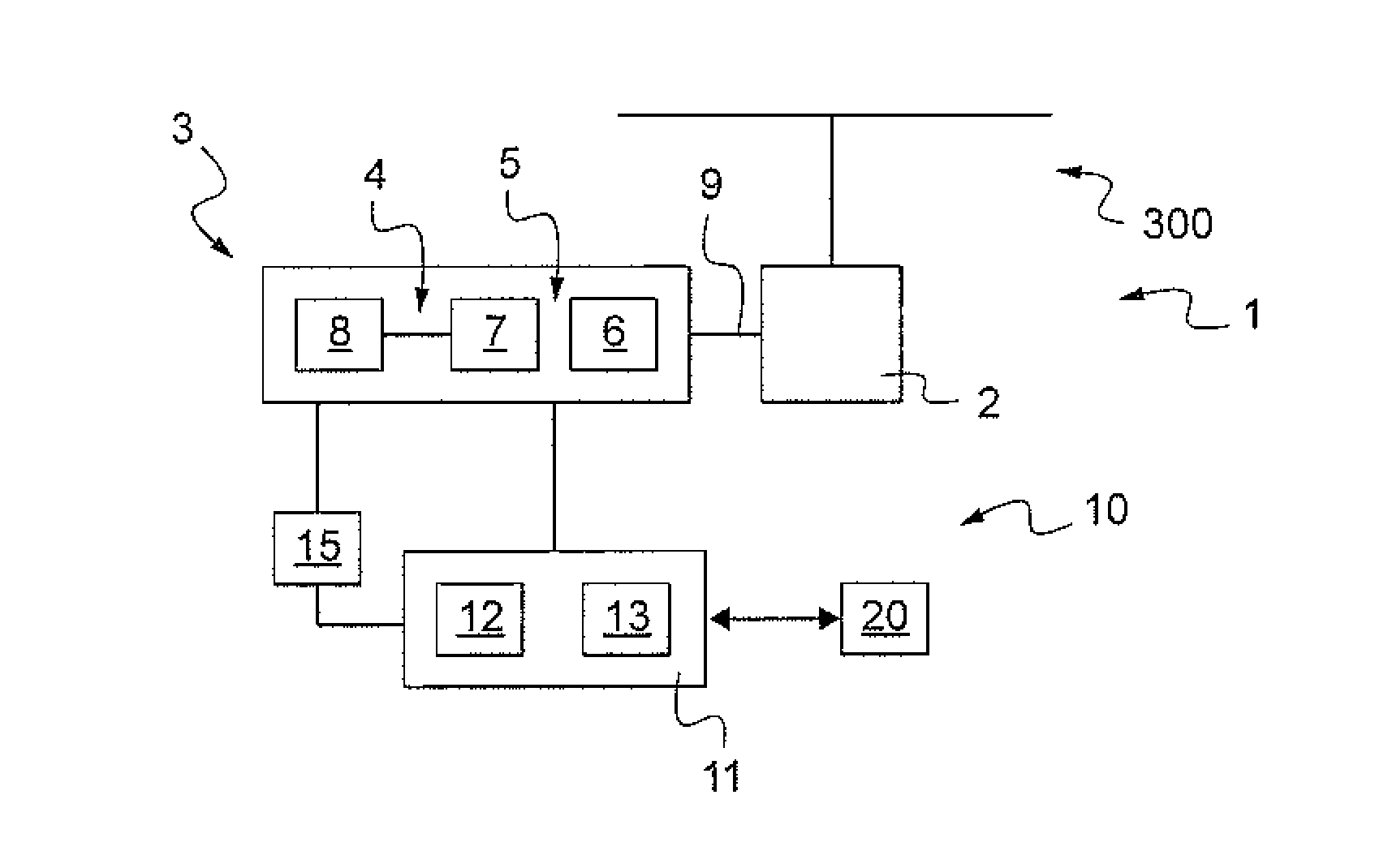
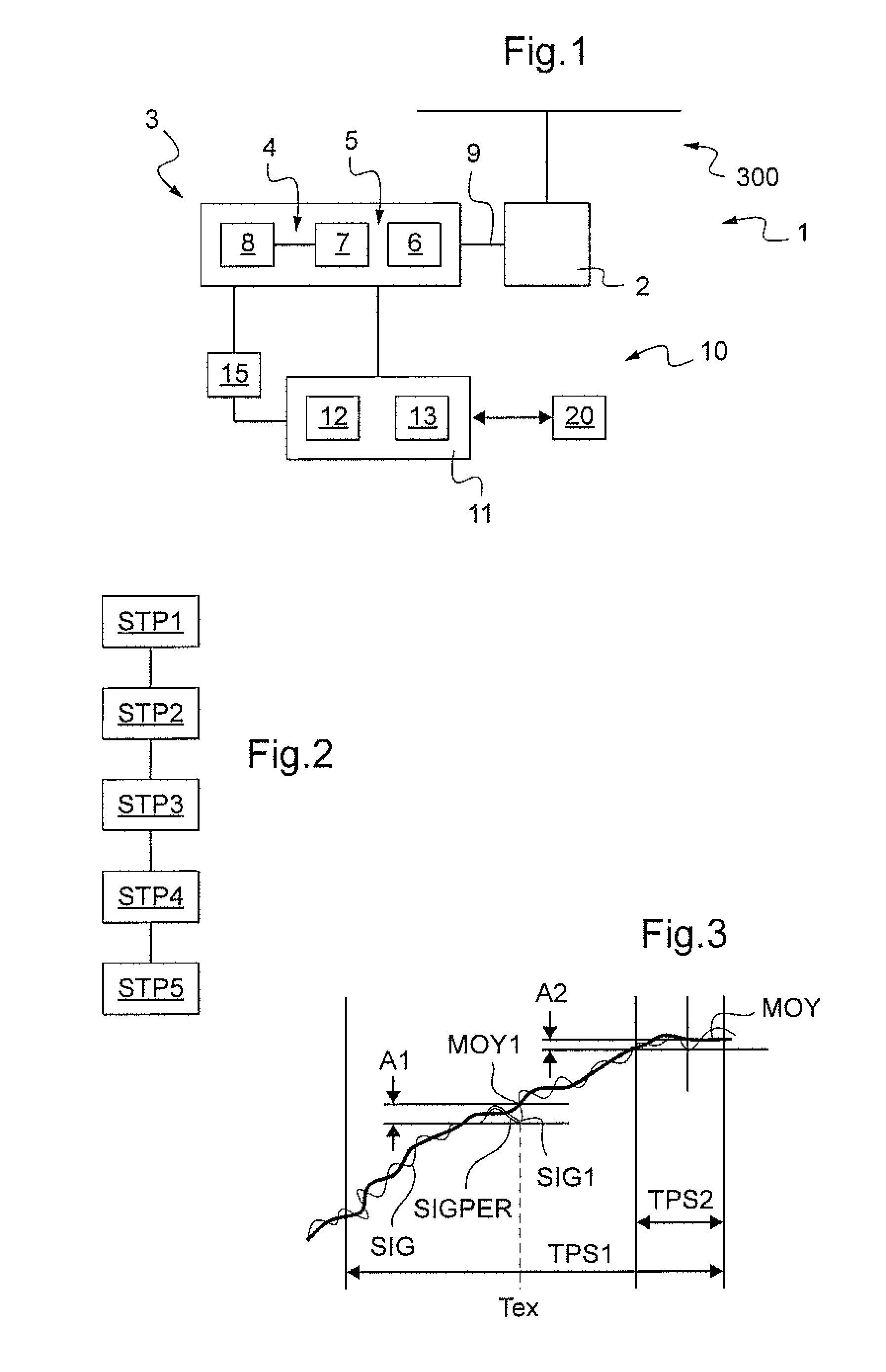
[0109]FIG. 1 shows an aircraft 1 provided with a rotary wing 300. However, the invention may also apply to some other type of aircraft.

[0110]The aircraft 1 has at least one turbine engine 3 for driving the rotary wing 300 via a main power transmission gearbox (MGB) 2. Each engine has a gas generator 4 and a turbine assembly 5.

[0111]For example, the gas generator comprises a compressor 8 co-operating with a high-pressure turbine 7 of the assembly 5.

[0112]In addition, the turbine assembly 5 includes a free turbine 6 that is connected to the MGB via a powertrain 9. For example, this powertrain 9 may be provided with an outlet shaft that is set into rotation by the free turbine.

[0113]More precisely, the aircraft 1 of FIG. 1 has one turboshaft engine 3.

[0114]Independently of the number of turbine engines, the invention proposes to perform automatically the check of the health of at least one turbine engine by means of a health-check device 10 of the aircraft.

[0115]With reference to FIG. ...


PUM


Abstract

A method of automatically performing an engine health check for checking the health of at least one turbine engine of an aircraft. During flight, the stability of at least one monitoring parameter is verified by acquiring a measurement signal, by performing first filtering of each signal by a high-pass filter over a long first duration (TPS1) and by verifying that a first amplitude (A1) of the signal filtered in this way does not exceed a first threshold defined by the manufacturer, by performing second filtering of each signal by a high-pass filter over a short second duration (TPS2) in parallel with said first filtering by a high-pass filter, and by verifying that a second amplitude (A2) of the signal filtered in this way does not exceed a second threshold defined by the manufacturer, the second duration (TPS2) being less than the first duration (TPS1), and the second amplitude (A2) being less than the first amplitude (A1).

Description

CROSS REFERENCE TO RELATED APPLICATIONS[0001]This application claims priority to French patent application No. FR 12 00341 filed on Feb. 6, 2012, the disclosure of which is incorporated in its entirety by reference herein.BACKGROUND OF THE INVENTION[0002](1) Field of the Invention[0003]The present invention relates to a method and to a device making it possible to perform a check of the state of health of a turbine engine arranged on an aircraft, said aircraft being provided with at least one turbine engine.[0004](2) Background Art[0005]Such an aircraft may be a rotary-wing aircraft, also known as a rotorcraft. However, the aircraft may also be an aircraft not provided with such a rotary wing.[0006]A rotorcraft is piloted while monitoring many instruments on the instrument panel. Most of the instruments represent operation of the power plant of the rotorcraft.[0007]For physical reasons, there are numerous limits that the pilot needs to take into account at each instant while flying....

Claims


Application Information

Patent Timeline
IPC IPC(8): F02C7/00
CPCF02C7/00F05D2260/821F05D2270/332F05D2270/803F05D2270/335G05B23/0221F05D2260/80F05D2270/304F05D2220/329F05D2270/303F02C9/00B64F5/00G01M15/14
Inventor CAMHI, EMMANUELBORCHERS, GUIDO
Owner EUROCOPTER
Learn More