Photo-acoustic tomography
a technology of photoacoustic tomography and image acquisition, applied in the field of photoacoustic tomography, can solve the problems of inability to acquire image of a cell positioned at a deep position, inability to scan an inner part through a high speed, and existing photoacoustic tomography, so as to reduce the system, increase the scanning speed, and increase the switching speed
- Summary
- Abstract
- Description
- Claims
- Application Information
AI Technical Summary
Benefits of technology
Problems solved by technology
Method used
Image

Examples
first exemplary embodiment
[0032]Hereinafter, a photo-acoustic tomography according to a first exemplary embodiment of the present invention will be described in detail with reference to FIG. 1.
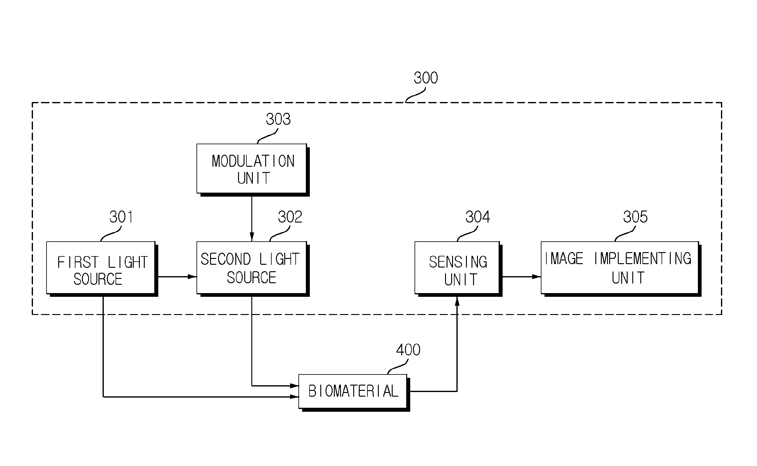
[0033]FIG. 1 is a block diagram illustrating a photo-acoustic tomography 100 according to a first exemplary embodiment of the present invention.
[0034]Referring to FIG. 1, the photo-acoustic tomography 100 includes a light source 101 outputting light; an amplification unit 102 amplifying and outputting the light output from the light source 101 to be absorbed in a biomaterial 200 which is an inspection target; a sensing unit 103 sensing an ultrasonic wave generated as the light output from the amplification unit 102 is absorbed in the biomaterial; and an image implementing unit 104 implementing an image of an inner part of the biomaterial 200 by using the ultrasonic wave sensed by the sensing unit 103.
[0035]Various examples of the light source 101 are available within a scope without departing from the spirit of the pre...
second exemplary embodiment
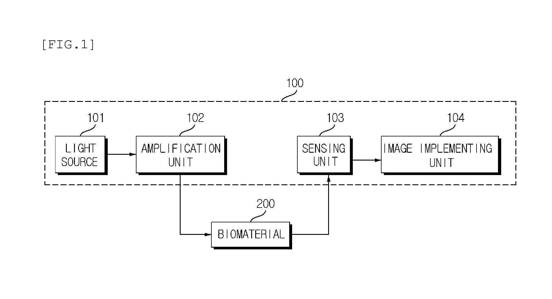
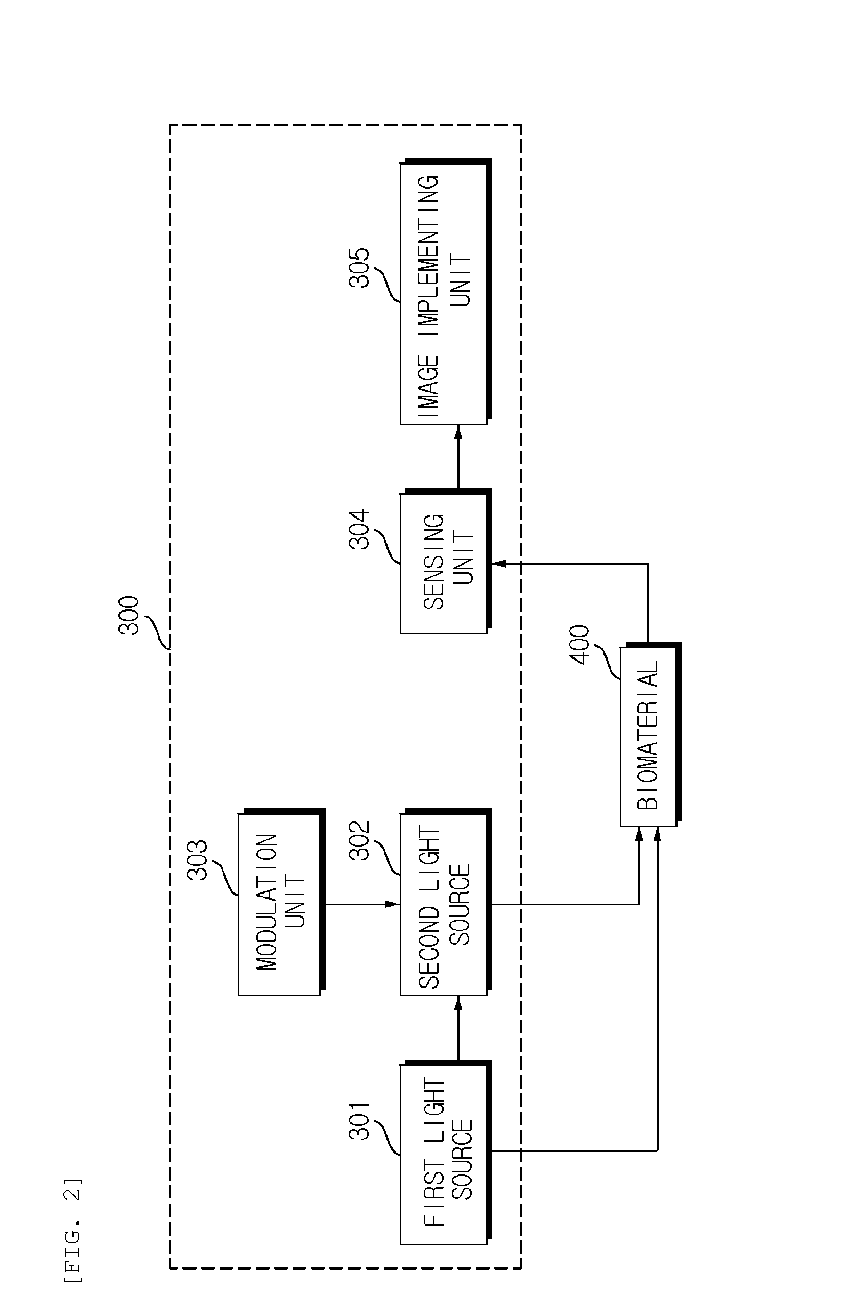
[0041]Hereinafter, a photo-acoustic tomography 300 according to a second exemplary embodiment of the present invention will be described in detail with reference to FIGS. 2 and 3.
[0042]FIG. 2 is a block diagram of the photo-acoustic tomography 300 according to the second exemplary embodiment of the present invention and FIG. 3 is a conceptual diagram for describing the photo-acoustic tomography 300 according to the second exemplary embodiment of the present invention.
[0043]The photo-acoustic tomography 300 according to the second exemplary embodiment of the present invention includes a light source 301 outputting first light (A of FIG. 3) to be absorbed in a biomaterial 400 which is an inspection target; a second light source 302 outputting second light (B of FIG. 3) which has power equal to or lower than the power of the first light and has a lower frequency than the first light to be absorbed in the biomaterial 400; a modulation unit 303 controlling the power and the frequency of ...
third exemplary embodiment
[0050]Hereinafter, a photo-acoustic tomography 500 according to a third exemplary embodiment of the present invention will be described in detail with reference to FIGS. 4 and 5.
[0051]FIG. 4 is a block diagram of the photo-acoustic tomography 500 according to the third exemplary embodiment of the present invention and FIG. 5 is a conceptual diagram for describing the photo-acoustic tomography 500 according to the third exemplary embodiment of the present invention.
[0052]The photo-acoustic tomography 500 according to the third exemplary embodiment of the present invention includes a light source array including first to n-th light sources 501a to 501n outputting first to n-th light to be absorbed in the biomaterial which is an inspection target; a sensor array including first to m-th sensors 502a to 502m sensing ultrasonic waves generated as the first to n-th light is absorbed in the biomaterial; and an image implementing unit 503 implementing an image of an inner part of the biomate...
PUM
 Abstract
Description
Claims
Application Information
 - R&D
- Intellectual Property
- Life Sciences
- Materials
- Tech Scout
- Unparalleled Data Quality
- Higher Quality Content
- 60% Fewer Hallucinations
Browse by: Latest US Patents, China's latest patents, Technical Efficacy Thesaurus, Application Domain, Technology Topic, Popular Technical Reports.
© 2025 PatSnap. All rights reserved.Legal|Privacy policy|Modern Slavery Act Transparency Statement|Sitemap|About US| Contact US: help@patsnap.com