
PTC Device and Secondary Battery Having the Same

Inactive Publication Date: 2013-08-01
LITTELFUSE JAPAN GK
View PDF11 Cites 9 Cited by
  • Summary
  • Abstract
  • Description
  • Claims
  • Application Information

AI Technical Summary

Benefits of technology

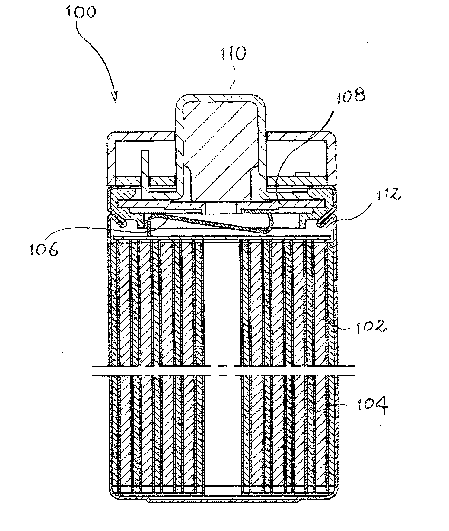
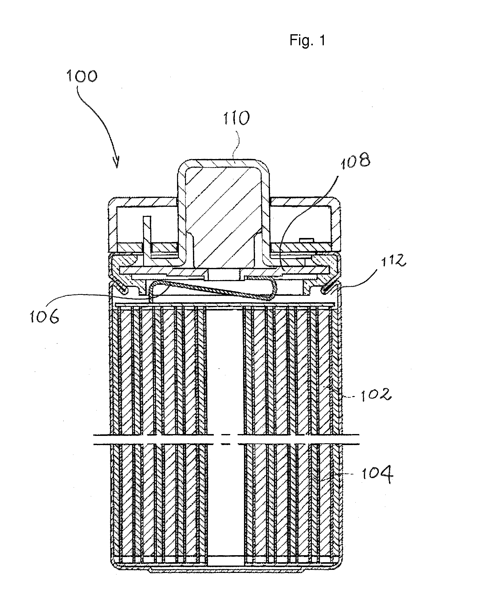
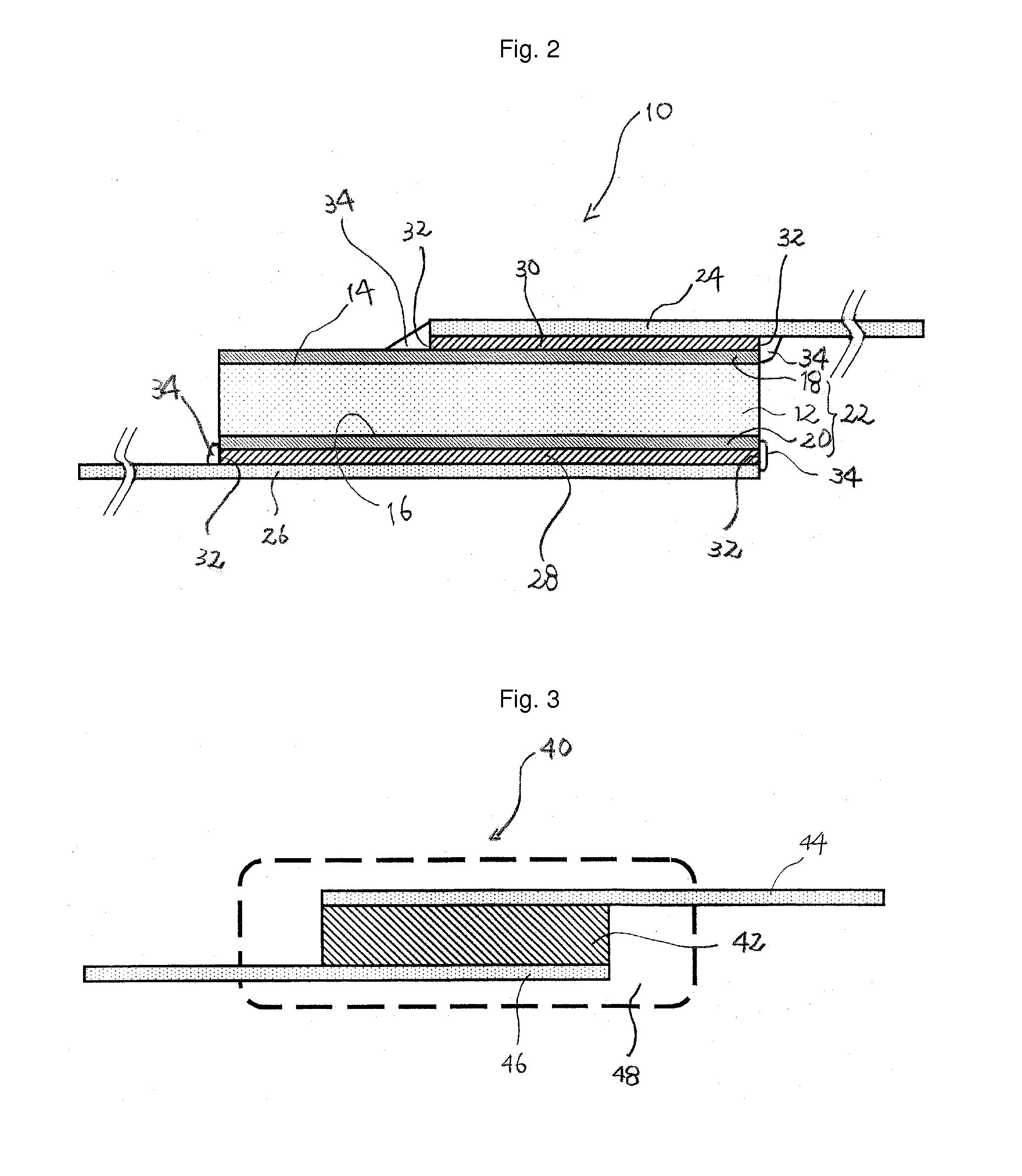
The present invention is related to a PTC device that can protect electronic circuits from corrosion caused by alkali in battery electrolyte. The device uses a protective member made of resins that have resistance to alkali, which prevents the alkali from reaching the electrically conductive material in the device. This results in minimal damage to the device and ensures its continued functioning as a circuit protection device. The PTC device can be placed in a space within the battery, such as the positive electrode tab space, which can save space within the battery.

Problems solved by technology

Such alkalis are generally corrosive so that the positive electrode tab is exposed to an environment of such alkaline.

Method used


Image

  • PTC Device and Secondary Battery Having the Same
  • PTC Device and Secondary Battery Having the Same
  • PTC Device and Secondary Battery Having the Same

Examples


example 1

[0047]A PTC device A of the present invention as shown in FIG. 4 was produced by thermal compression-binding a PTC component sandwiched by films (provided that the end of the lead was exposed). During the thermal compression binding, only the film portion extending outside from around the PTC component was pressed so that force would not be applied to the PTC component (the lead section was pressed).

[0048]The film used was a laminated film of a polypropylene resin layer and a polyethylene resin layer (thickness: 100 μm). This film was used so that the polypropylene resin layer was on the outside.

[0049]Other conditions are shown below:

[0050]PTC component used (trade name: PolySwitch, manufactured by Tyco Electronics Japan G.K.)

[0051]Lead: nickel (trade name: NB201, manufactured by Neomax Co., Ltd., thickness: 150 μm)

[0052]Conductive material: lead-free solder (alloy solder of tin, silver and copper) Thermal compression binding condition: Pressed for 10-40 seconds at a temperature of ...

example 2

[0053]A PTC device B of the present invention shown in FIG. 3 was produced by using the same PTC component as Example 1 and insert-molding a polypropylene resin. The polypropylene resin used was, the trade name: Prime Polypro, manufactured by Prime Polymer Co., Ltd. The conditions for the PTC device B were the same as for the PTC device A except for the protective member.

[0054]The PTC devices A and B thus obtained were subjected to an alkali immersion experiment which was conducted by immersing them in a KOH aqueous solution (1N) at 60° C. for 3 months. The condition of the interface between the protective member and the lead was observed to evaluate the effect of alkali. A holding current test (I-V test) was performed on the PTC devices after the immersion. Also, for comparison, the same test was conducted on other PTC components having the same specification as the PTC components used in the production of the PTC devices. The results are shown below:

PTC device APTC device BRinitia...


PUM


Abstract

A PTC device as well as an electrical device such as a battery pack or a dry-cell type secondary cell containing a PTC device and a secondary cell is made more compact. The PTC device includes (1) a PTC component including a laminar polymer PTC element having an electrically conductive filler and a polymer material, and a metal electrode disposed on a surface of each side of the polymer PTC element; and (2) a lead positioned at least in part on the metal electrode of the PTC component, and connected to the metal electrode by an electrically conductive material. An exposed part of the electrically conductive material is covered by a protective member including a polypropylene resin, a nylon resin or an epoxy resin.

Description

TECHNICAL FIELD[0001]The present invention relates to a PTC device as well as an electrical device, for example a secondary battery, comprising same.BACKGROUND ART[0002]A polymer PTC component, comprising a laminar PTC element containing a conductive filler and a polymer material, and a metal electrode disposed on a surface of each side of the polymer PTC element, is widely used in various electrical devices. For example, such a PTC component is used as a circuit protection device in a secondary battery charging circuit in order to prevent a problem of overcharging and the like when a secondary battery of a cell phone is charged. This PTC component is disposed in a protection circuit via leads, and a PTC device comprising the PTC component and the leads, and the protection circuit are disposed outside the positive electrode terminal; these together make up an electrical device, and are used as the so-called a “battery pack”. Since an electrical apparatus has the battery pack embedde...

Claims


Application Information

Patent Timeline
IPC IPC(8): H01C7/02H01M10/42H01M50/574
CPCH01C1/1406H01C7/027H01M2/34H01C1/028H01M2200/106H01C7/02H01M10/425H01M2/348Y02E60/10H01M50/581H01M50/574H01M50/572
Inventor TANAKA, ARATAYAMAOKA, TOSHIKAZUMIYAGI, HARUHISA
Owner LITTELFUSE JAPAN GK
Learn More