Vehicle speed determination via infrared imaging

a technology of infrared imaging and speed determination, applied in the direction of electric/magnetic computing, analogue processes for specific applications, instruments, etc., can solve the problems of inability to place vehicle features at fixed heights, and the speed calculated by analyzing non-stereo images taken of moving vehicles tends to lack the accuracy required for law enforcement, so as to eliminate trigonometric calculations for height correction, accurate speed detection, and high contrast

Active Publication Date: 2013-07-25
CONDUENT BUSINESS SERVICES LLC
View PDF6 Cites 8 Cited by
  • Summary
  • Abstract
  • Description
  • Claims
  • Application Information

AI Technical Summary

Benefits of technology

This patent describes a system and method that uses infrared imaging to detect the point where a vehicle's tire touches the road surface, allowing for accurate speed detection. This method eliminates the issue of uneven feature height across vehicles, making the measurement easier. Overall, the invention improves real-time speed detection for vehicles.

Problems solved by technology

Unfortunately, vehicle features are not placed at fixed heights across all vehicle makes and models.
As such, speeds calculated by analyzing non-stereo images taken of moving vehicles tend to lack the accuracy required for law enforcement.

Method used


Image

  • Vehicle speed determination via infrared imaging
  • Vehicle speed determination via infrared imaging
  • Vehicle speed determination via infrared imaging

Examples


example networked embodiment

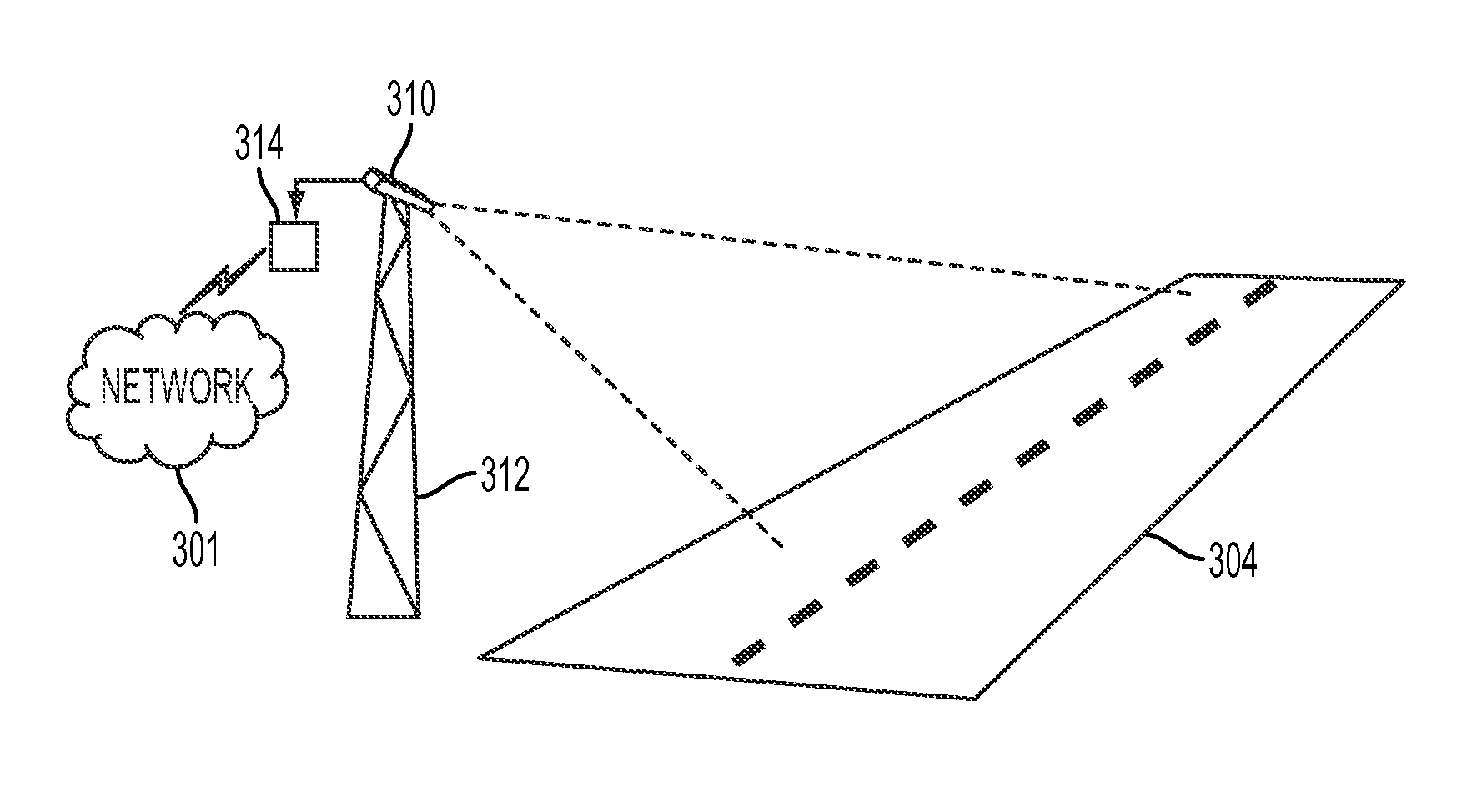
[0029]Reference is now being made to FIG. 4 which illustrates the embodiment of FIG. 3 wherein further aspects of the present system are illustrated.

[0030]IR camera system 310 and controller 314 may incorporate wired and / or wireless elements and may be connected via other means such as cables, radio, or any other manner for communicating known in the arts. Network 301 can receive signals transmitted from tower 411 and wirelessly communicates those signals to any of: workstation 413, graphical display device 414, and / or multi-function print system device 415. Signal transmission system 411 is also in wireless communication with handheld cellular device 416 and tablet 417. Workstations 413 and 414 are in communication with each other and multi-function document reproduction device 415 over network 301 including devices 416 and 417 and IR camera system 310 and controller 314. Such a networked environment may be wholly incorporated within the confines of a single building or may be dist...

example captured

IR images

[0034]Reference is now being made to FIG. 5, which is a series of three related FIGS. 5a, 5b and 5c. FIG. 5a and FIG. 5b show two IR images captured of a target vehicle 116 travelling on a road 304, using the IR imaging system shown and discussed with respect to the embodiments of FIGS. 3 and 4. The IR images may be still images that are captured at different times, or they may be separate frames taken from a video sequence. Using standard calibration procedures, pixels within these images may be converted to real-world coordinates. However, since a 3-dimensional real-world scene is projected onto a 2-dimensional image, there is inherently some loss of information, unless a stereo imaging system is used, wherein pairs of images from two different positions are captured. The discussion here is limited to non-stereo images. Using procedures known in the art, it is possible to uniquely determine two of the dimensions if the third dimension is known. For example, if the height ...


PUM


Abstract

A system and method which detects and uses a point of contact between a vehicle's tire and the pavement as a reference point to improve the accuracy of vehicle speed detection in a motorized vehicle speed detection system. In one embodiment, a plurality of infrared images of a moving vehicle are received. Each of the images is separated in time by known intervals. The images are captured using an infrared camera which can be a single-band or multi-band camera which operates in an infrared wavelength band selected to enhance a contrast between the vehicle's tires and the road surface. For each image, a point of contact is determined where a same tire contacts the road surface. These points and the time interval separations are used to calculate the vehicle's speed. An alert signal is initiated to a traffic enforcement authority if the speed exceeds the road's speed limit.

Description

TECHNICAL FIELD[0001]The present invention is directed to systems and methods for determining a speed of a vehicle by tracking vehicle features in a sequence of images captured over a known time interval or frame rate.BACKGROUND[0002]Methods for vehicle speed detection using video have many important transportation applications. For applications such as traffic speed enforcement, accurate speed detection is necessary. One method for determining a vehicle's speed is to capture two time-sequenced images of that vehicle, track a specific feature on that vehicle such as, for example, a location of the vehicle's license plate, and then calculate the vehicle's speed from trigonometric relationships. For accurate speed determination, the precise height above the road surface of the feature being tracked needs to be known in advance, unless a stereo imaging system is used, wherein pairs of images from two different positions are captured. Unfortunately, vehicle features are not placed at fi...

Claims


Application Information

Patent Timeline
IPC IPC(8): G08G1/052
CPCG08G1/054G08G1/0116G06K9/2018G08G1/052
Inventor DALAL, EDUL N.WU, WENCHENG
Owner CONDUENT BUSINESS SERVICES LLC
Why Eureka
Try Eureka