Revolution speed transducer

A technology of speed sensor and pressure sensor, applied in the direction of devices using electric/magnetic methods, etc., can solve the problems of increasing angular velocity detection error, improper detection of another axis, and non-parallel between the instrument panel and the ground.

Inactive Publication Date: 2015-09-09
陆宇
View PDF0 Cites 3 Cited by
  • Summary
  • Abstract
  • Description
  • Claims
  • Application Information

AI Technical Summary

Problems solved by technology

However, many vehicles have dashboards that are not parallel to the ground
In the case where the control system is installed in an inclined instrument panel, the detection axis of the rotational speed sensor is also inclined, the detection error of the angular velocity becomes large, and similarly, improper detection of the other axis occurs more frequently

Method used


Image

  • Revolution speed transducer
  • Revolution speed transducer
  • Revolution speed transducer

Examples


Embodiment Construction

[0014] The present invention will be further described below in conjunction with accompanying drawing.

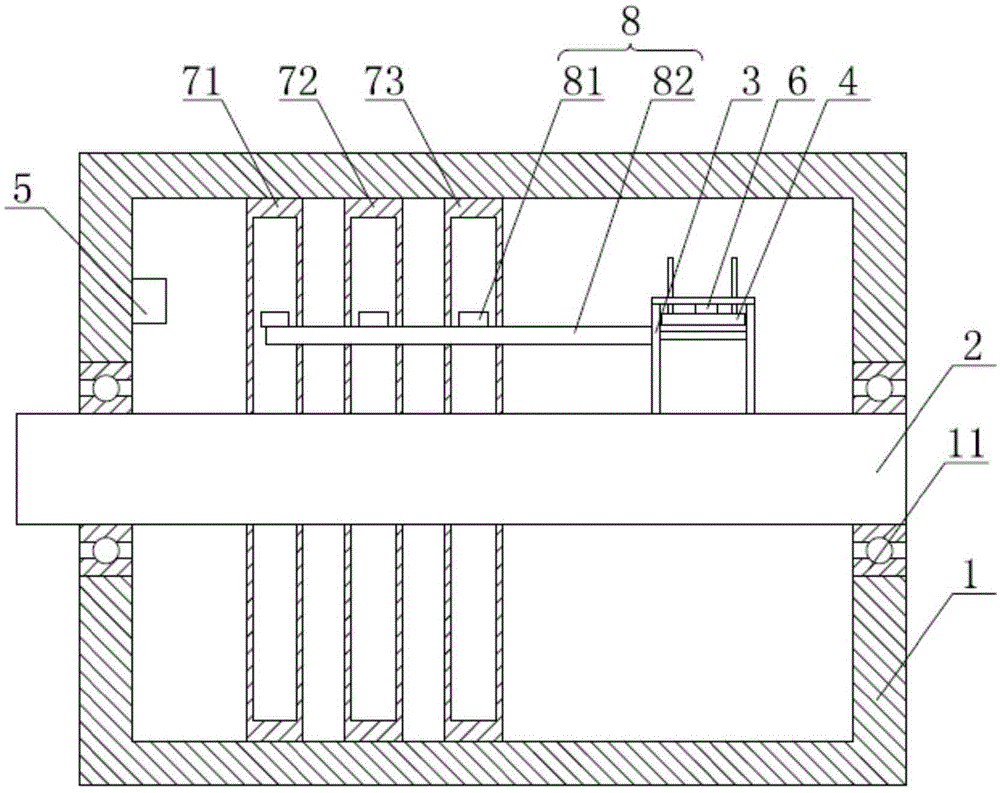
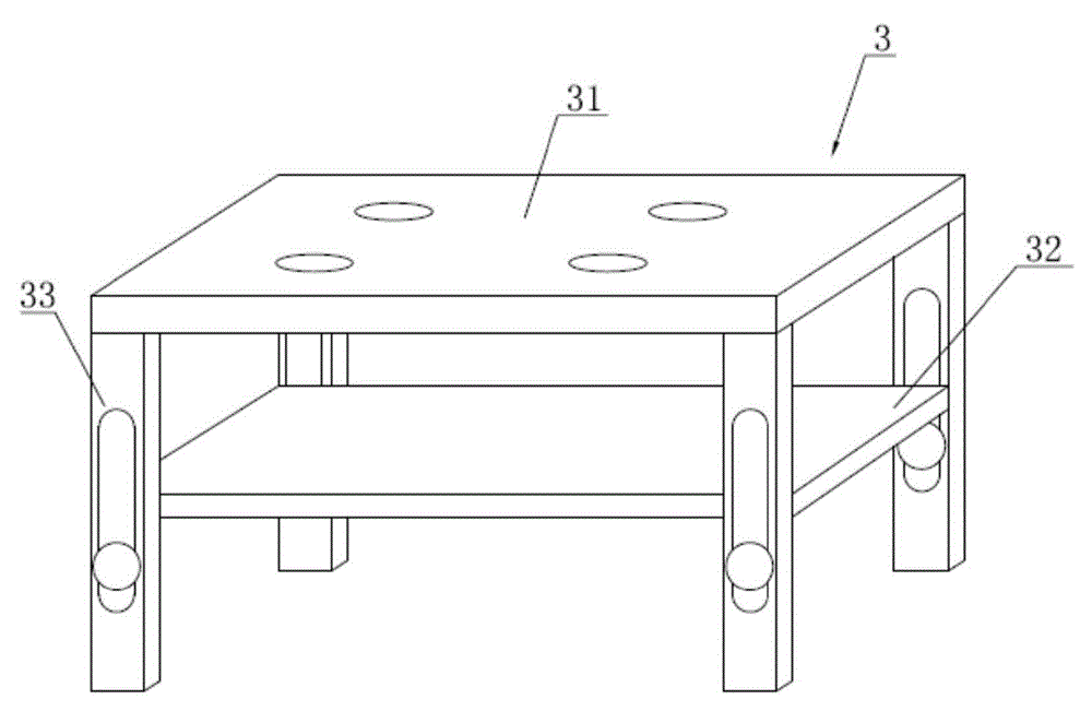
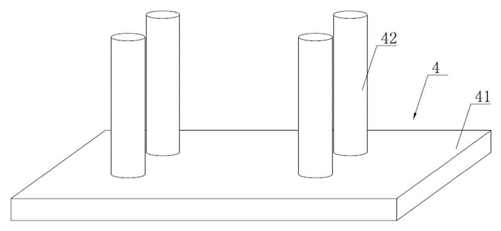
[0015] Such as figure 1 As shown, the preferred embodiment of the speed sensor of the present invention includes a body 1, a rotating shaft 2 connected to the wheel shaft, a base frame 3 fixed on the rotating shaft 2, a pressure plate 4, a microprocessor 5 and a pressure sensor 6, the rotating shaft 2 fixed on the body 1, and the rotating shaft 2 can rotate relative to the body 1, the pressure sensor 6 is fixed on the base frame 3, the pressure plate 4 is movably connected in the base frame 3, the body 1 is provided with a signal chute 71, a power input chute 72 and an output chute 73, and the pressure sensor 6 is electrically connected to the signal chute 71, the power input chute 72 and the output chute 73 through a brush 8, so The microprocessor 5 is electrically connected to the signal chute 71 and the power input chute 72 and the output chute 73, the brush device 8 in...


PUM


Abstract

The present invention discloses a revolution speed transducer. The revolution speed transducer comprises a body, a rotating shaft connected with a wheel axle, a base frame fixed on the rotating shaft, a pressing plate, a microprocessor and a pressure sensor, wherein the rotating shaft is fixed on the body and is rotatable in relative to the rotating shaft, the pressure sensor is fixed on the base frame, the pressing plate is movably connected inside the base frame, the body is internally provided with a signal sliding chute and power supply input and output sliding chutes, the pressure sensor is electrically connected with the signal sliding chute and the power supply input and output sliding chutes through an electric brush device, and the microprocessor is electrically connected with the signal sliding chute and the power supply input and output sliding chutes. According to the revolution speed transducer, signals detected by the pressure sensor is sent to the microprocessor, processed and calculated, so as to obtain revolution speed, with no need for detection using the ground as the criterion, and angular speed of wheels may be accurately detected.

Description

technical field [0001] The invention relates to a speed detection device, in particular to a rotational speed sensor. Background technique [0002] The rotational speed sensor detects the angular velocity of an object as it rotates. Rotational speed sensors are used to avoid image blur caused by hand movement when taking pictures, and are used in position detection systems such as car navigation systems, and attitude control systems for cars and robots. Any inclination of the inspection axis relative to the inspection datum will result in inspection errors or improper inspection of the other axis. In the above case, accurate angular velocity cannot be detected. Therefore, a control system equipped with a rotational speed sensor suffers from various problems caused by angle detection errors. For example, for a vehicle navigation system, a rotational speed sensor is usually mounted in the instrument panel of the vehicle. [0003] In the case where the control system equipp...

Claims


Application Information

Patent Timeline
Patent Type & Authority Applications(China)
IPC IPC(8): G01P3/44
Inventor 陆宇
Owner 陆宇
Why Eureka
Try Eureka