
Magnetic shape optimization

a technology of magnetic shape and optimization, applied in the direction of manufacturing tools, electrical-based machining electrodes, working accessories, etc., can solve the problems of low mechanical strength, high waste of materials, and high cost of raw materials

Active Publication Date: 2013-07-11
APPLE INC
View PDF13 Cites 13 Cited by
  • Summary
  • Abstract
  • Description
  • Claims
  • Application Information

AI Technical Summary

Benefits of technology

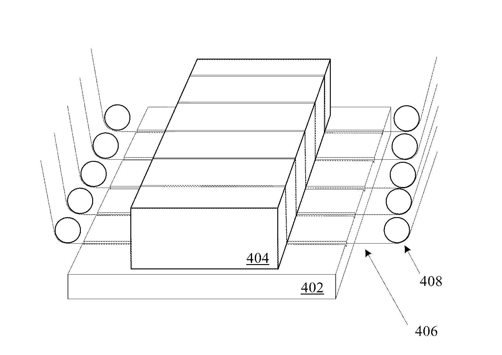
The patent describes a method and apparatus for machining magnets with complementary surfaces. The technical effects include a multi-wire cutting machine that simultaneously cuts multiple magnets, a workpiece holder that securely holds a magnetic substrate, and a working fluid application mechanism that immerses the cutting wires with working fluid. Another embodiment of the patent describes a machining method that uses two sets of parallel cutting wires to cut a magnetic substrate into multiple magnets with complementary surfaces. A computer readable medium is also provided for controlling the wire spooling rate, wire cutting speed, and wire path of the cutting wires. Overall, the technical effects include improved efficiency and accuracy in the machining of magnets with complementary surfaces.

Problems solved by technology

Magnets made from ceramic materials are quite brittle, resulting in a low mechanical strength.
In many cases the cost of raw materials is quite high; therefore, any waste of material is highly undesirable.
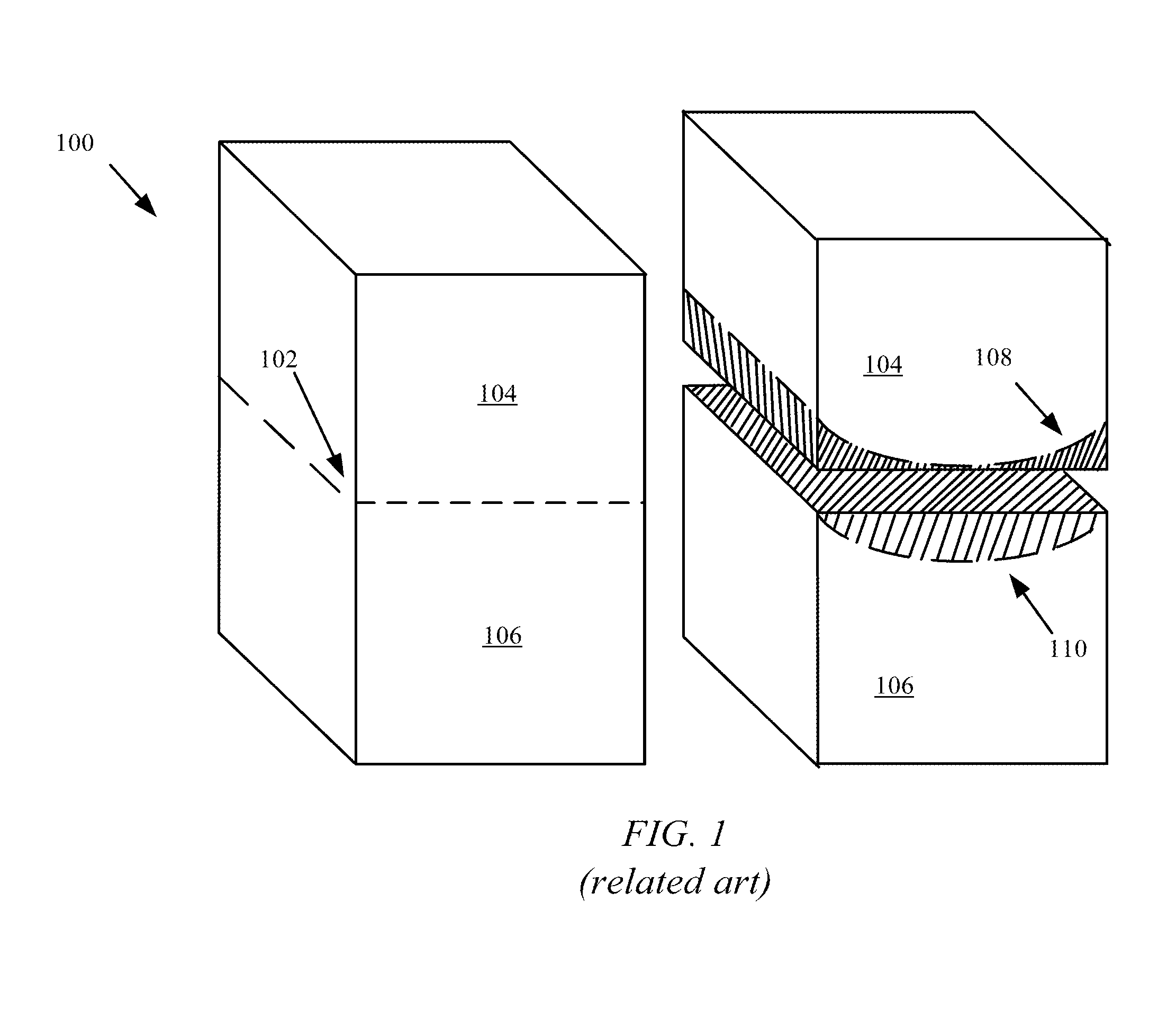
Unfortunately, conventional diamond saws are generally limited to creating straight cuts.
In many cases the grinding and polishing necessary to achieve a non-linear surface adds a significant amount of extra time and labor to the manufacturing process.
Moreover, since the raw materials of a magnet can be quite costly, grinding away material in a manner that essentially destroys the excess material is highly undesirable.

Method used


Image

  • Magnetic shape optimization
  • Magnetic shape optimization
  • Magnetic shape optimization

Examples


Embodiment Construction

[0024]Representative applications of methods according to the present application are described in this section. These examples are being provided solely to add context and aid in the understanding of the described embodiments. It will thus be apparent to one skilled in the art that the described embodiments may be practiced without some or all of these specific details. In other instances, well known process steps have not been described in detail in order to avoid unnecessarily obscuring the described embodiments. Other applications are possible, such that the following examples should not be taken as limiting.

[0025]In the following detailed description, references are made to the accompanying drawings, which form a part of the description and in which are shown, by way of illustration, specific embodiments in accordance with the described embodiments. Although these embodiments are described in sufficient detail to enable one skilled in the art to practice the described embodimen...


PUM

PropertyMeasurementUnit
thicknessaaaaaaaaaa
thicknessaaaaaaaaaa
widthaaaaaaaaaa

Abstract

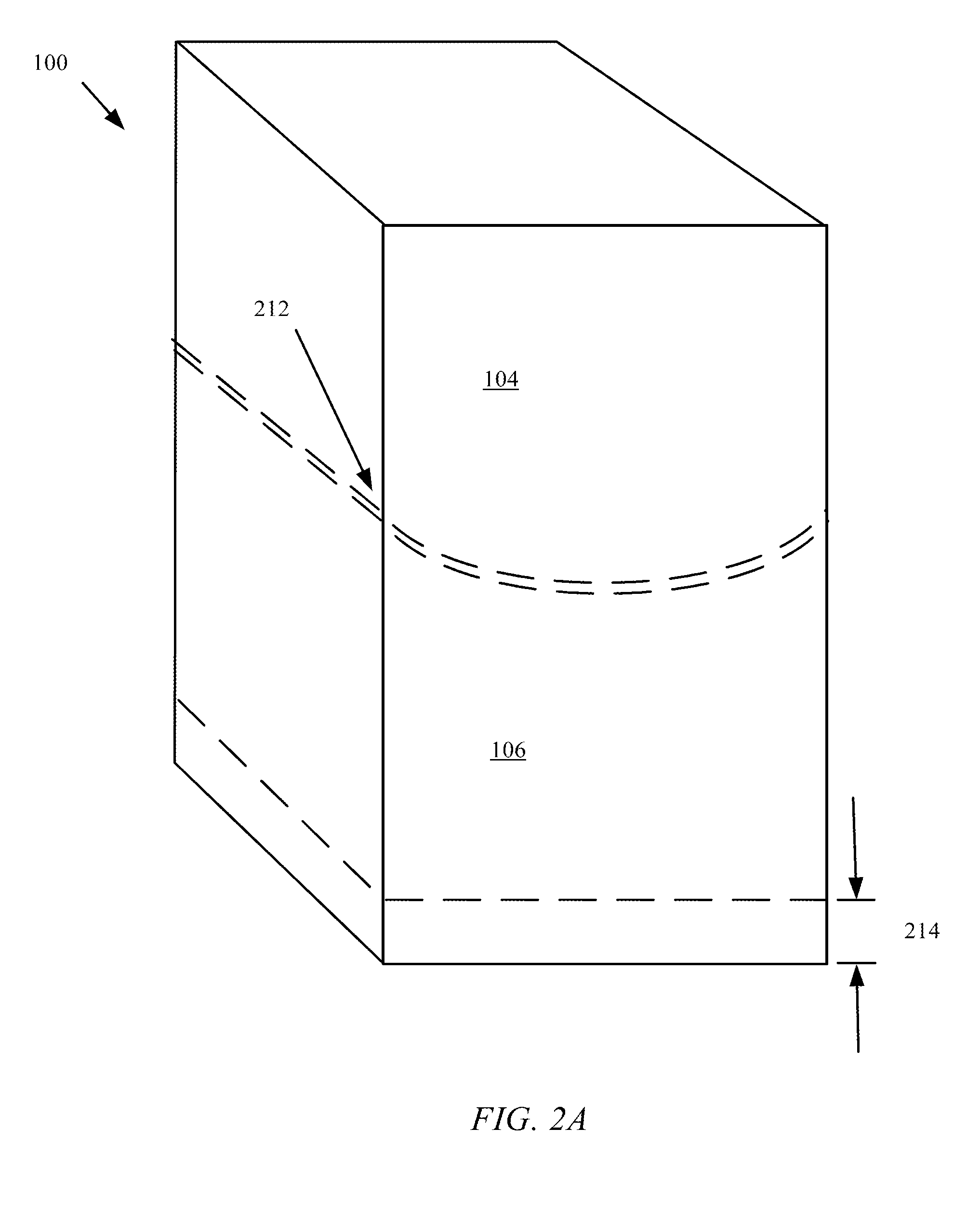
A method for efficiently machining magnets with curved surfaces is disclosed. The use of machining equipment capable of making curved cuts through magnetic material can allow significant cost and material savings, particularly when machining magnets with complementary surfaces. A process for using a series of cutting wires to simultaneously cut magnetic material into conformally shaped magnets is described.

Description

CROSS-REFERENCE TO RELATED APPLICATION[0001]This application claims priority to and benefit under 35 U.S.C. 119(e) of U.S. Provisional Patent Application No. 61 / 584,760, filed Jan. 9, 2012, and entitled “MAGNETIC SHAPE OPTIMIZATION”, the entire disclosure of which is hereby incorporated by reference.BACKGROUND[0002]1. Technical Field[0003]This disclosure relates generally to methods for minimizing material waste when cutting complex magnet shapes.[0004]2. Related Art[0005]Magnets made from ceramic materials are quite brittle, resulting in a low mechanical strength. Because of this material property, special cutting tools are used when machining this particular class of magnets in order to prevent cracking or fracture of the magnets during the machining process. In many cases the cost of raw materials is quite high; therefore, any waste of material is highly undesirable. Diamond saws, which consist of diamond coated discs of roughly 0.3-0.4 millimeters in width are a common tool empl...

Claims


Application Information

Patent Timeline
Patent Type & Authority Applications(United States)
IPC IPC(8): H01F41/02B28D1/02B23H1/00B28D1/00
CPCH01F41/0253B28D1/00B28D1/02B23H1/00Y10T29/49789B28D1/041B28D1/08B23H7/10B23D57/0023
Inventor LANCASTER-LAROCQUE, SIMON REGIS LOUISSATCHER, RYAN M.
Owner APPLE INC
Learn More