Dispensing Nozzle for Autoanalyzer, Autoanalyzer Equipped with the Nozzle, and Method for Producing Dispensing Nozzle for Autoanalyzer
a technology for autoanalyzers and nozzles, which is applied in chemical methods analysis, laboratory glassware, instruments, etc., can solve the problems of inability to use methods, difficult to wash away biopolymers such as proteins in specimens, and affecting measurement results, so as to improve the analytical reliability of autoanalyzers, improve the cleanliness of the surface of the nozzle, and reduce the amount of specimens and reagents
- Summary
- Abstract
- Description
- Claims
- Application Information
AI Technical Summary
Benefits of technology
Problems solved by technology
Method used
Image
Examples
example 1
[0039](Structure of Analyzer)
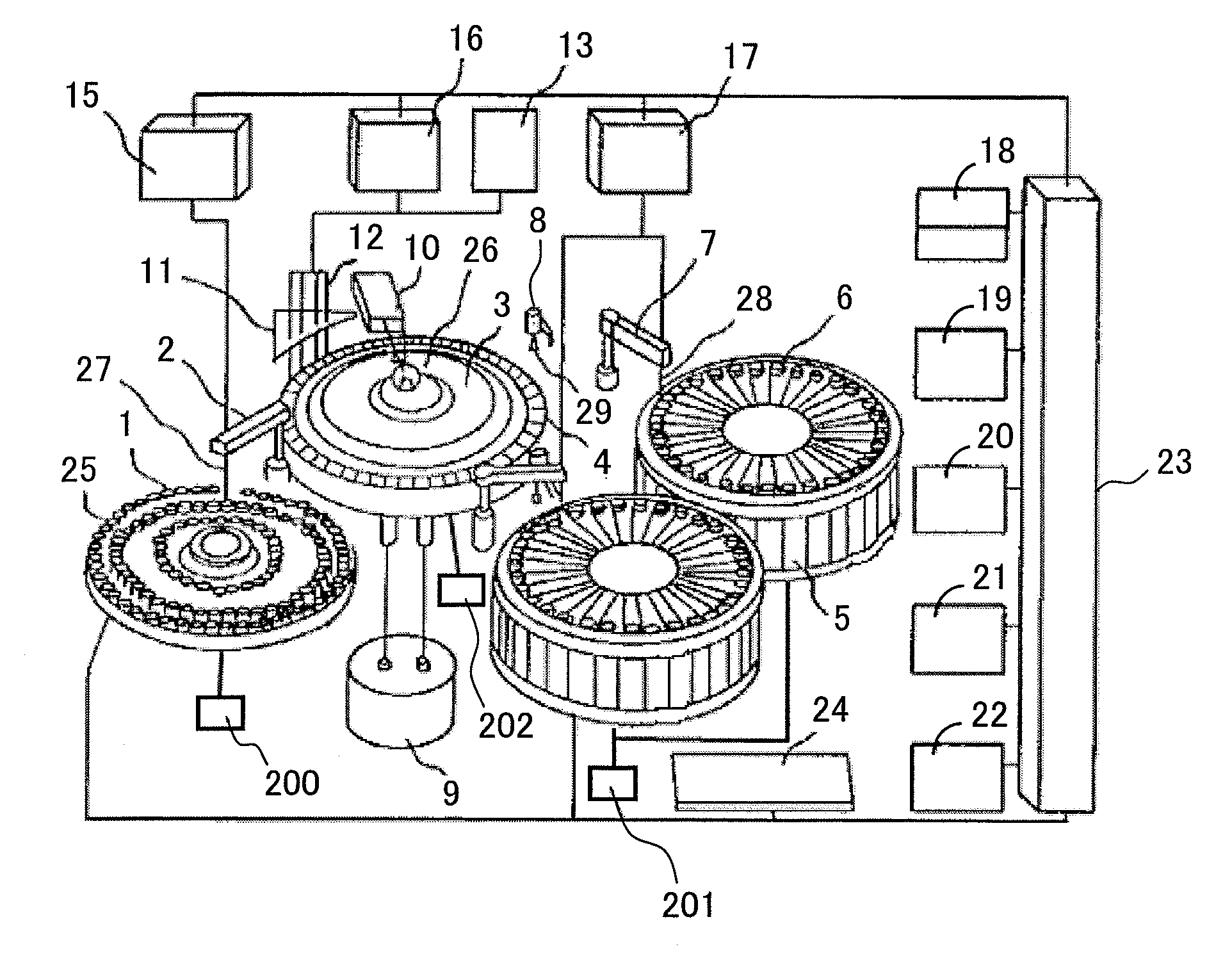
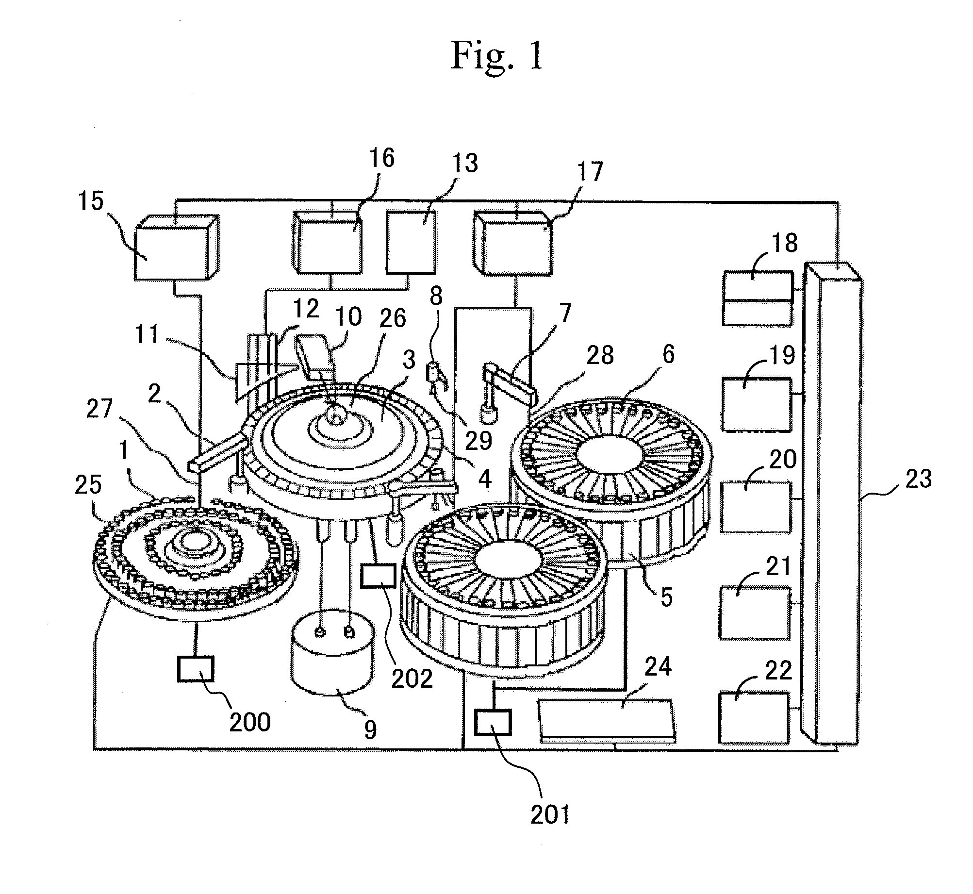
[0040]FIG. 1 shows a structure of an autoanalyzer according to the present invention. In the autoanalyzer, a specimen storage mechanism 1 is disposed. In the specimen storage mechanism 1, one or more specimen containers 25 are arranged. The specimen storage mechanism 1 shown in FIG. 1 is a so-called specimen disk mechanism, in which the specimen containers 25 can detachably installed in a disk-form main body. However, in the specimen storage mechanism 1, other mechanisms such as a specimen rack or a specimen holder that is generally used in an autoanalyzer can be used.
[0041]The specimen herein refers to a test solution to be reacted in the reaction container and may be a collected specimen as it is, or a solution of the collected specimen diluted or processed by pretreatment or the like. The specimen in the specimen container 25 is extracted by a specimen dispensing nozzle 27 of a dispensing mechanism for specimen supply 2 and injected into a predetermin...
experimental example 1
[0074]First, to enhance reliability of analysis, effect was verified by use of a planar substrate. The size of the substrate used was 30 mm×30 mm×0.5 mm. For verifying the effect, a measurement surface of 30 mm×30 mm was used.
[0075]A flowchart of a surface treatment process is shown in FIG. 5.
[0076]Step 1. Washing of Stainless Steel
[0077]A SUS304 substrate was ultrasonically washed with a 0.1% NaOH aqueous solution and ethanol for 15 minutes and washed with water. Thereafter, the SUS304 substrate was dried by nitrogen blowing.
[0078]Step 2. Soaking in a Solution of a Phosphonic Acid Derivative
[0079]The SUS304 substrate washed in Step 1 is soaked in a solution of a phosphonic acid derivative for 24 hours. Thereafter, the substrate is taken out from the solution, washed with a solvent and then washed with pure water. Thereafter, the SUS304 substrate is dried by nitrogen blowing.
[0080]The verification of the effect was carried out by estimating the adsorption amount of protein component...
experimental example 2
[0081]In the case of Experimental Example 1 described above, surface treatment was performed in a single-stage reaction process of adsorbing a phosphonic acid derivative. In this Experimental Example 2, a process for performing a surface treatment in multiple stages will be described.
[0082]FIG. 7 shows a flowchart of a surface treatment process. The surface treatment process is constituted of roughly two treatment steps. A first one is a step of coating the surface of stainless steel with a phosphonic acid derivative having a reactive functional group at a terminal and the second one is a step of immobilizing a molecule having a desired function to the reactive functional group.
[0083]In this Experimental Example, at first, a method of immobilizing a phosphonic acid having a carboxyl group at a terminal to a nozzle surface and then rendering the carboxyl group to be reactive will be described. Note that, as a molecule for suppressing protein adsorption, a polyethylene glycol (PEG) de...
PUM
 Abstract
Description
Claims
Application Information
 - R&D
- Intellectual Property
- Life Sciences
- Materials
- Tech Scout
- Unparalleled Data Quality
- Higher Quality Content
- 60% Fewer Hallucinations
Browse by: Latest US Patents, China's latest patents, Technical Efficacy Thesaurus, Application Domain, Technology Topic, Popular Technical Reports.
© 2025 PatSnap. All rights reserved.Legal|Privacy policy|Modern Slavery Act Transparency Statement|Sitemap|About US| Contact US: help@patsnap.com


