Composition for forming liquid crystal layer, liquid crystal display device, and method for producing liquid crystal display device
a liquid crystal display and liquid crystal technology, applied in the field of liquid crystal display devices, can solve problems such as problematically increasing response time and display darkness, and achieve the effect of low degradation of parts and high reliability
- Summary
- Abstract
- Description
- Claims
- Application Information
AI Technical Summary
Benefits of technology
Problems solved by technology
Method used
Image

Examples
embodiment 1
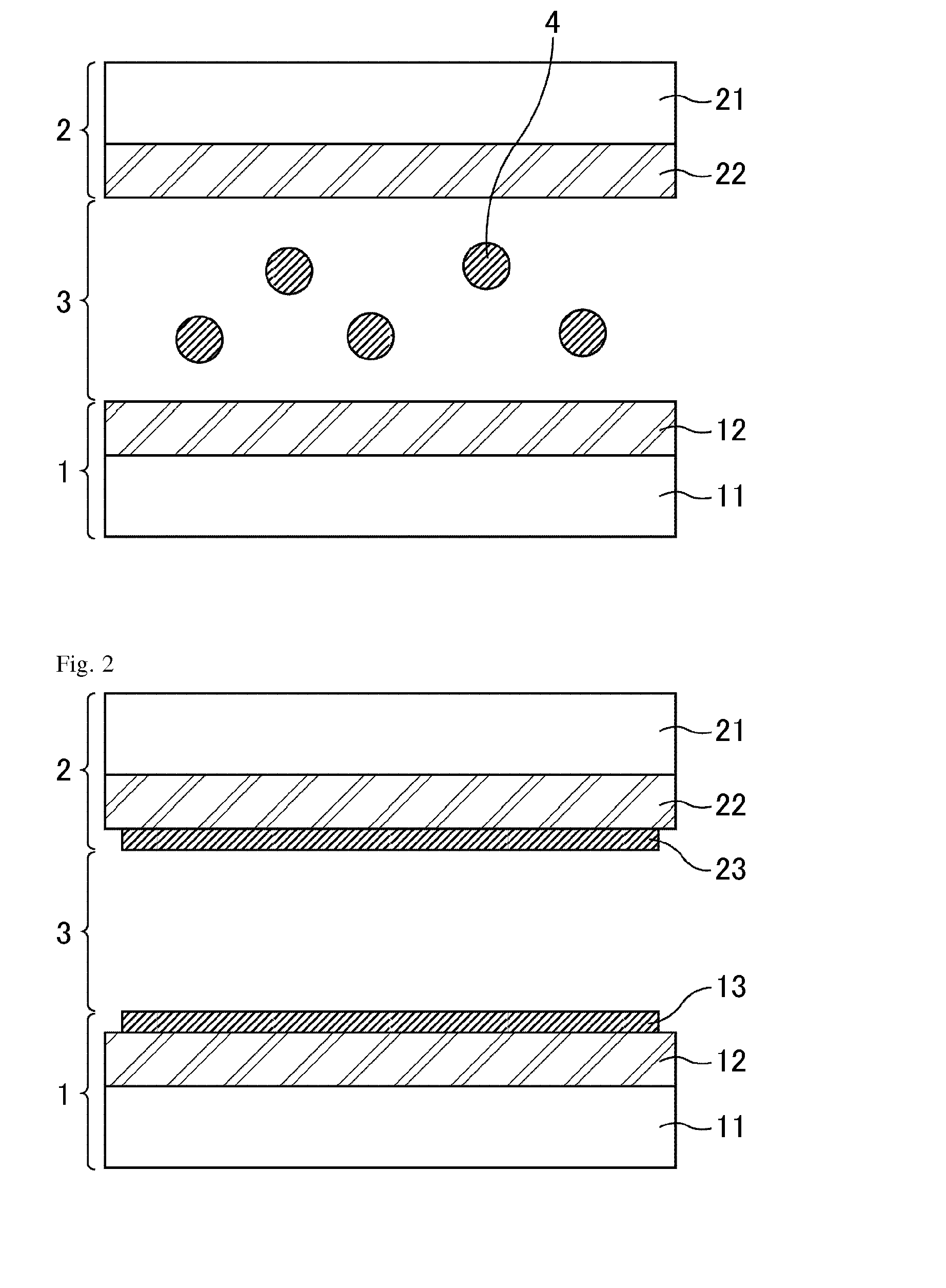
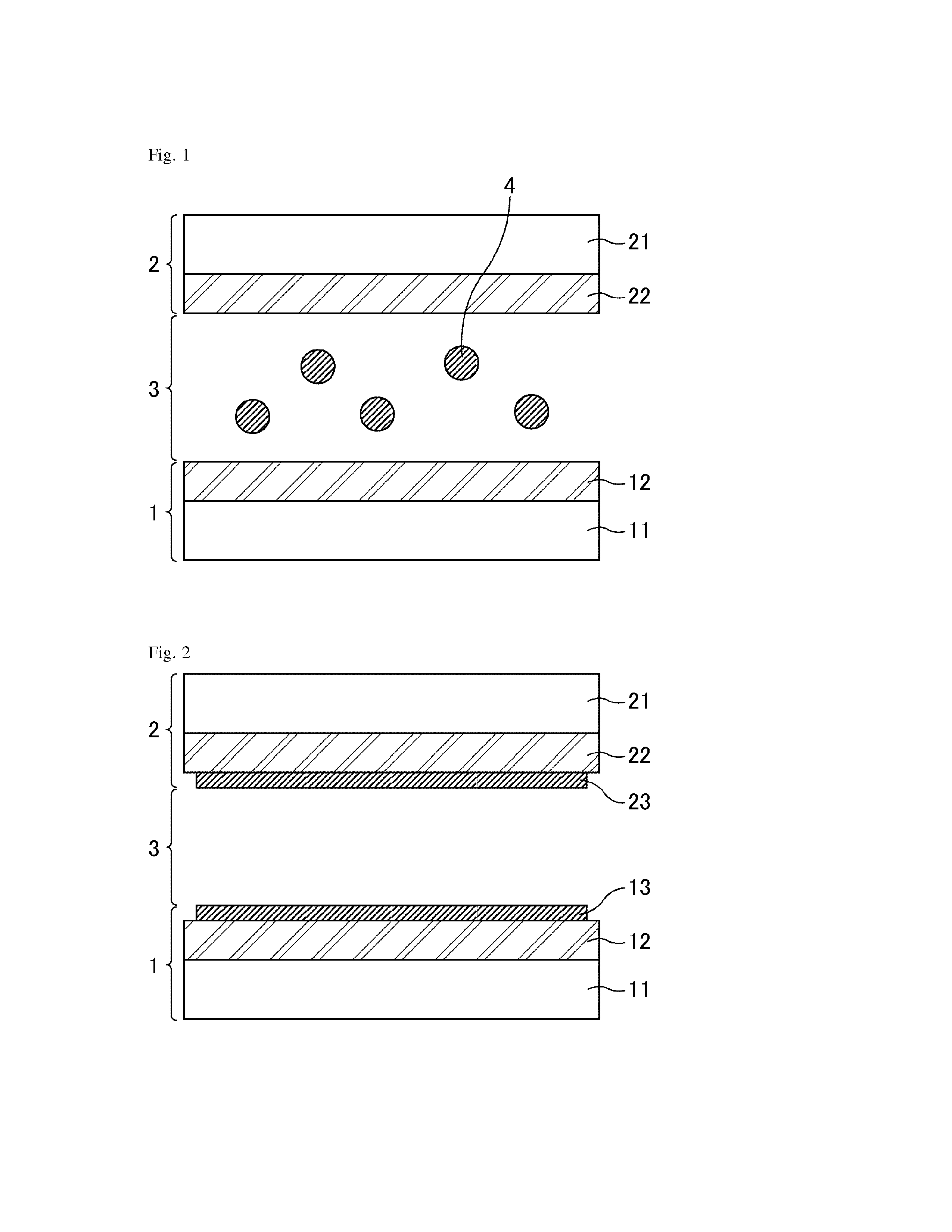
[0088]FIG. 1 and FIG. 2 each are a cross sectional view schematically illustrating a liquid crystal display device according to Embodiment 1. FIG. 1 illustrates the liquid crystal display device before the PSA polymerization step, and FIG. 2 illustrates the liquid crystal display device after the PSA polymerization step. As shown in FIG. 1 and FIG. 2, the liquid crystal display device according to Embodiment 1 includes an array substrate 1, a color filter substrate 2, and a liquid crystal layer 3 disposed between a pair of the substrates consisting of the array substrate 1 and the color filter substrate 2. The array substrate 1 includes an insulating transparent substrate made of glass, or the like, and a support substrate 11 that is formed on the transparent substrate and is provided with various wirings, pixel electrodes, a TFT (Thin Film Transistor), or the like. The color filter substrate 2 includes an insulating transparent substrate made of glass, or the like, and a support su...
example 1
[0105]The following will discuss Example 1 in which a liquid crystal cell included in the liquid crystal display device according to Embodiment 1 was actually produced. First, a pair of support substrates were prepared. A polyamic acid solution as a material of a vertical alignment film was applied to the surfaces of the pair of support substrates, followed by pre-baking at 80° C. for five minutes and subsequent post-baking at 200° C. for sixty minutes to produce a polyimide.
[0106]Next, an alignment treatment was performed on the alignment film after post-baking. Next, a seal was applied to a single-sided substrate. Then a composition for forming a liquid crystal layer that contained liquid crystal materials having negative dielectric constant anisotropy and a monomer for forming a PSA layer was dropped onto the single-sided substrate. Thereafter, the other substrate was laminated on the composition.
[0107]In Example 1, a combination of monomers represented by the chemical formulae (...
synthesis example 1
Synthesis of 4,4-dimethacryloyloxybenzophenone (the chemical formula (6)
[0109]An amount of 4.0 g of 4,4′-dihydroxybenzophenone was dissolved in 24 g of THF, and 4.7 g of triethylamine was added thereto. Then, 4.8 g of methacrylic acid chloride was dropwise added to the mixture over 30 minutes, followed by stirring for one hour. To the stirred solution was added 170 g of a 196-HCl aqueous solution, then extracted with 120 g of methylene chloride, and separated and washed with water. Thereafter, methylene chloride was distilled away, and the resultant was purified by silica gel column chromatography (ethyl acetate:hexane=1:5) to thereby give 4.5 g of a target 4,4′-dimethacryloyloxybenzophenone. The reaction path is represented by the following chemical reaction formula (7).
[0110]The following samples A to E were prepared in Example 1. In the sample A, the composition for forming liquid crystal layers contains 0.3 wt % of the bifunctional biphenyl monomer represented by the chemical fo...
PUM
| Property | Measurement | Unit |
|---|---|---|
| pre-tilt angle | aaaaa | aaaaa |
| wavelength | aaaaa | aaaaa |
| wavelength | aaaaa | aaaaa |
Abstract
Description
Claims
Application Information
 - R&D
- Intellectual Property
- Life Sciences
- Materials
- Tech Scout
- Unparalleled Data Quality
- Higher Quality Content
- 60% Fewer Hallucinations
Browse by: Latest US Patents, China's latest patents, Technical Efficacy Thesaurus, Application Domain, Technology Topic, Popular Technical Reports.
© 2025 PatSnap. All rights reserved.Legal|Privacy policy|Modern Slavery Act Transparency Statement|Sitemap|About US| Contact US: help@patsnap.com