
Nanowire catalysts and methods for their use and preparation

a technology of nanowire catalysts and nanowires, which is applied in the direction of metal/metal-oxide/metal-hydroxide catalysts, lanthanide oxides/hydroxides, bulk chemical production, etc., can solve the problem of reducing the yield of undesired side products, affecting the adsorption rate of reactants, and affecting the adsorption rate, so as to improve the legibility of the drawing

Active Publication Date: 2013-06-27
LUMMUS TECH LLC
View PDF0 Cites 121 Cited by
  • Summary
  • Abstract
  • Description
  • Claims
  • Application Information

AI Technical Summary

Benefits of technology

The patent text describes a new type of catalyst that can be used in petrochemical processes. The catalyst is made up of nanowires that have been doped with different elements. The doping elements can include metals, semi-metals, non-metals, and other elements like K, Na, Zr, and more. The nanowires can also be combined with other dopants like K, Na, Zr, and more. The technical effect of this new catalyst is that it can improve the efficiency and selectivity of petrochemical processes.

Problems solved by technology

Thus, at a given temperature, a positive catalyst tends to increase the yield of desired product while decreasing the yield of undesired side products.
Although catalysts are not consumed by the reaction itself, they may be inhibited, deactivated or destroyed by secondary processes, resulting in loss of catalytic activity.
This transport and adsorption of reactants is often the rate limiting step in a heterogeneous catalysis reaction.
In addition, homogeneous catalysts can be difficult to separate from the reaction mixture.
While there are multistep paths to convert methane to certain specific chemicals using first; high temperature steam reforming to syngas (a mixture of H2 and CO), followed by stochiometry adjustment and conversion to either methanol or, via the Fischer-Tropsch (F-T) synthesis, to liquid hydrocarbon fuels such as diesel or gasoline, this does not allow for the formation of certain high value chemical intermediates.
This multi-step indirect method also requires a large capital investment in facilities and is expensive to operate, in part due to the energy intensive endothermic reforming step.
It is also inefficient in that a substantial part of the carbon fed into the process ends up as the GHG CO2, both directly from the reaction and indirectly by burning fossil fuels to heat the reaction.
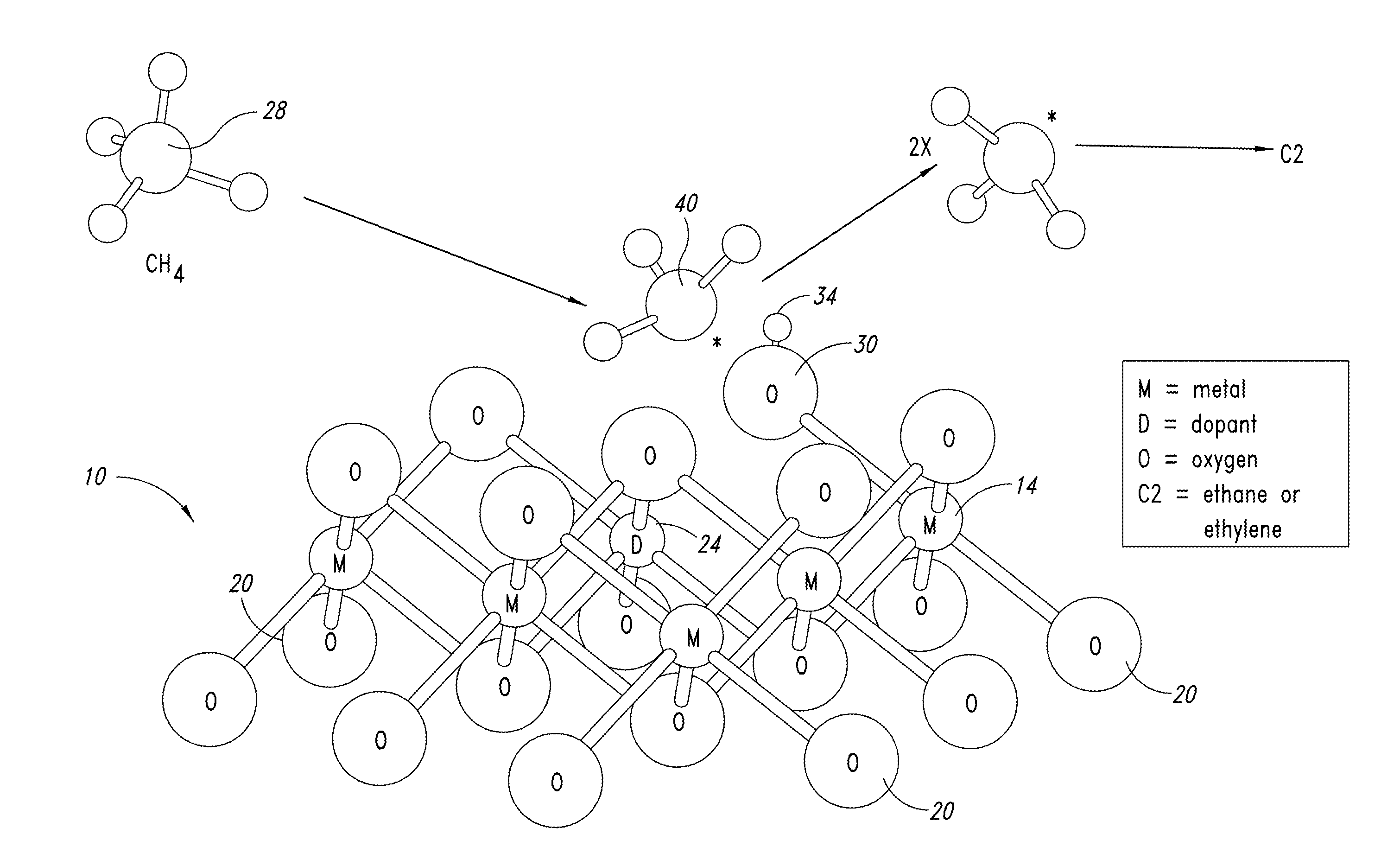
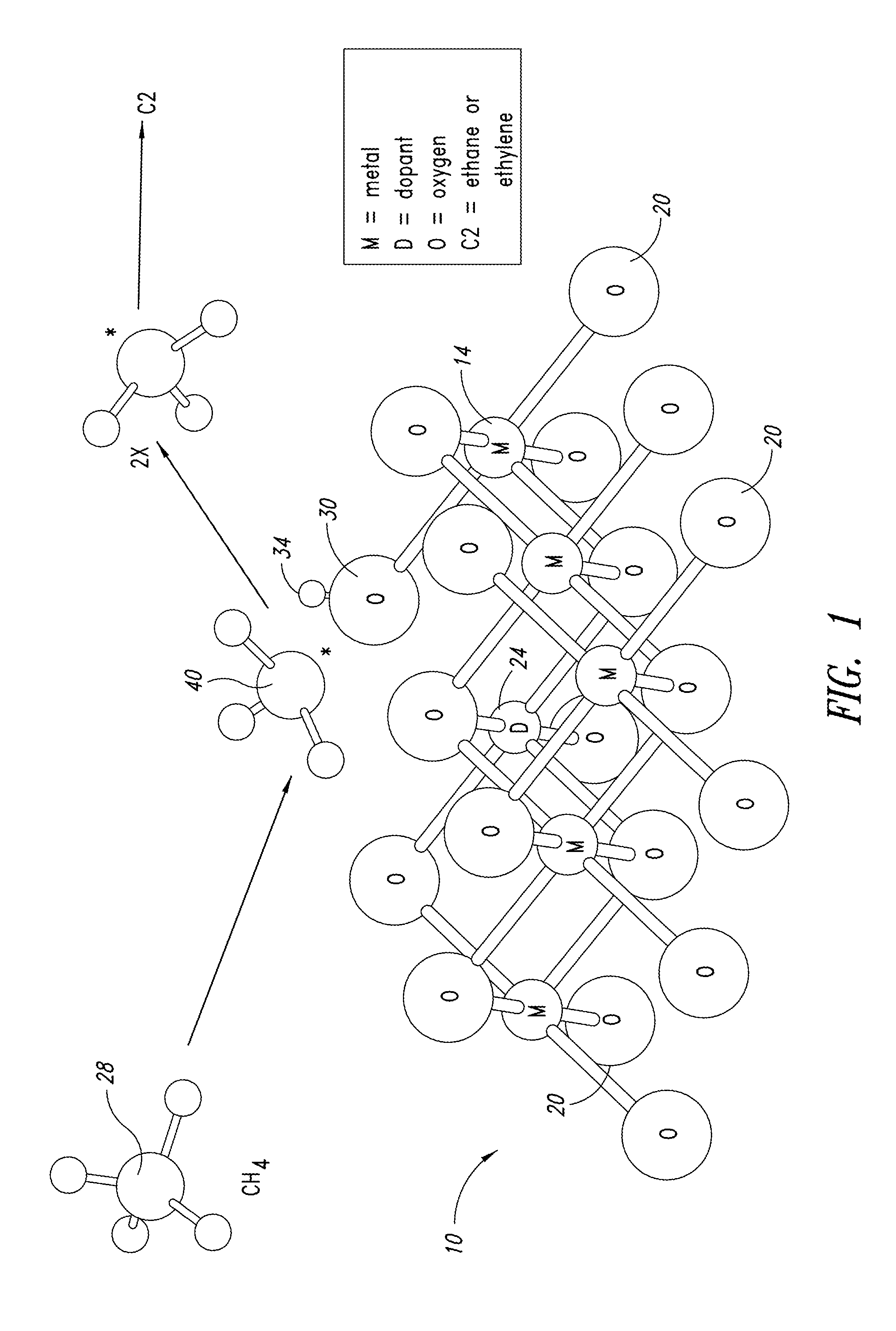
Since the OCM reaction was first reported over thirty years ago, it has been the target of intense scientific and commercial interest, but the fundamental limitations of the conventional approach to C—H bond activation appear to limit the yield of this attractive reaction.

Method used


Image

  • Nanowire catalysts and methods for their use and preparation
  • Nanowire catalysts and methods for their use and preparation
  • Nanowire catalysts and methods for their use and preparation

Examples


example 1

Genetic Engineering / Preparation of Phage

[0658]Phage were amplified in DH5 derivative E. coli (New England Biolabs, NEB5-alpha F′ Iq; genotype: F″ proA+B+lacIq Δ(lacZ)M15 zzf::Tn10 (TetR) / fhuA2Δ(argF-lacZ)U169 phoA gInV44 φ80Δ(lacZ)M15 gyrA96 recA1 endA1 thi-1 hsdR17) and purified using standard polyethylene glycol and sodium chloride precipitation protocols as described in the following references: Kay, B. K.; Winter, J.; McCafferty, J. Phage Display of Peptides and Proteins: A Laboratory Manual; Academic Press: San Diego (1996); C. F. Barbas, et al., ed., Phage Display: A Laboratory Manual; Cold Spring Harbor Laboratory Press, Cold Spring Harbor, N.Y., USA (2001); and Joseph Sambrook and David W. Russell, Molecular Cloning, 3rd edition, Cold Spring Harbor Laboratory Press, Cold Spring Harbor, N.Y., USA, 2001.

example 2

Preparation of Phage Solutions

[0659]The phage solutions were additionally purified by centrifuging at an acceleration of 10000 g at least once (until no precipitated material was observed), decanting the supernatant and splitting it in 50 ml containers, which were then stored frozen at −20° C. The frozen phage solutions were thawed only shortly before being used.

[0660]The concentration of the phage solutions was measured using a UV-VIS spectrometer. The concentration of each of the frozen phage aliquots was measured prior to use. This spectroscopic method relies on the absorption of the nucleotides in the DNA of the phage and is described in more detail in “Phage Display: A Laboratory Manual” by Barbas, Burton, Scott and Silverman (Cold Spring Harbor Laboratory Press, 2001). The concentration of phage solutions is expressed in pfu / ml (plague forming units per milliliter).

example 3

[0661]Preparation Mg(OH)2 Nanowires

[0662]FIG. 12 shows a generic reaction scheme for preparing MgO nanowires (with dopant). First, the phage solution is thawed and its concentration determined according to the method described above. The phage solution is diluted with water to adjust its concentration in the reaction mixture (i.e. with all the ingredients added) to the desired value, typically 5e12 pfu / ml or higher. The reaction container can be anything from a small vial (for milliliter scale reactions) up to large bottles (for liter reaction scale reactions).

[0663]A magnesium solution and a base solution are added to the phage solution in order to precipitate Mg(OH)2. The magnesium solution can be of any soluble magnesium salt, e.g. MgX2.6H2O (X═Cl, Br, I), Mg(NO3)2, MgSO4, magnesium acetate, etc. The range of the magnesium concentration in the reaction mixture is quite narrow, typically at 0.01M. The combination of the phage concentration and the magnesium concentration (i.e. the...


PUM

PropertyMeasurementUnit
diameteraaaaaaaaaa
TEMaaaaaaaaaa
lengthaaaaaaaaaa

Abstract

Nanowires useful as heterogeneous catalysts are provided. The nanowire catalysts are useful in a variety of catalytic reactions, for example, the oxidative coupling of methane to C2 hydrocarbons. Related methods for use and manufacture of the same are also disclosed.

Description

CROSS-REFERENCES TO RELATED APPLICATIONS[0001]This application claims the benefit under 35 U.S.C.§119(e) of U.S. Provisional Patent Application No. 61 / 564,834, filed on Nov. 29, 2011; Provisional Patent Application No. 61 / 564,836, filed on Nov. 29, 2011; and U.S. Provisional Patent Application No. 61 / 651,399, filed on May 24, 2012; each of which are incorporated herein by reference in their entireties.STATEMENT REGARDING SEQUENCE LISTING[0002]The Sequence Listing associated with this application is provided in text format in lieu of a paper copy, and is hereby incorporated by reference into the specification. The name of the text file containing the Sequence Listing 860158—420_SEQUENCE_LISTING.txt. The text file is 19 KB, was created on Nov. 29, 2012, and is being submitted electronically via EFS-Web.BACKGROUND[0003]1. Technical Field[0004]This invention is generally related to novel nanowire catalysts and, more specifically, to nanowires useful as heterogeneous catalysts in a varie...

Claims


Application Information

Patent Timeline
Patent Type & Authority Applications(United States)
IPC IPC(8): B01J23/34B01J23/30B01J21/10B01J23/04B01J21/06B01J23/22B01J23/10B01J23/02
CPCB01J23/30B82Y30/00B01J23/04B01J37/031B01J37/08B01J37/10B01J21/066B01J21/10B01J23/10B01J23/22B01J23/34B01J35/0013B01J35/06B01J37/0018C01F5/02C01F5/08C01F5/14C01F17/0043C01P2002/52C01P2002/72C01P2004/04C01P2004/16C01P2004/54C01P2006/12C01G25/02C01G31/02C01G45/02C01G45/1221C01P2004/80C07C2/84C07C2523/30C07C2523/22C07C2523/10C07C2523/34C07C2523/02C07C2521/10C07C2521/06C07C2523/04B01J23/02Y02P20/52Y10S977/762C01F17/241C01F17/229C01F17/224B01J35/58B01J35/45C07C11/04C01F17/206B01J35/23
Inventor ZURCHER, FABIO R.SCHER, ERIK C.CIZERON, JOEL M.SCHAMMEL, WAYNE P.TKACHENKO, ALEXGAMORAS, JOELKARSHTEDT, DMITRYNYCE, GREGRUMPLECKER, ANJAMCCORMICK, JARODMERZLYAK, ANNAALCID, MARIANROSENBERG, DANIELRAS, ERIK-JAN
Owner LUMMUS TECH LLC
Learn More