
Device and method for joining a composite and metallic material

Inactive Publication Date: 2013-05-23
HYUNDAI MOTOR CO LTD
View PDF8 Cites 27 Cited by
  • Summary
  • Abstract
  • Description
  • Claims
  • Application Information

AI Technical Summary

Benefits of technology

The present invention provides a device and method for joining carbon fiber / polymer composite and metallic materials. The joint is designed to increase strength and stability, prevent detachment and shear stresses, and improve aesthetic appearance. The joint is formed through a two-step process involving adhesive and screws, resulting in a smooth and linear construction.

Problems solved by technology

However, the conventional joint methods as described above commonly have a disadvantage in that since stresses are concentrated on the joint point between the ends of the carbon fiber composite and the metallic material, the joint strength is poor.
However, the attachment of the above-mentioned reinforcements does not greatly relieve the stress concentration.
That is, for example, the bolt / nut, which is a kind of reinforcement, has a disadvantage in that since the head and threads of the bolt are in contact with the carbon fiber composite and do not have a high ultimate strain when a compressive force is applied, fractures may be initiated from the carbon fiber composite.
In addition, in the above mentioned joint methods, since the ends of the carbon fiber composite and the metallic material are overlapped with each other at different heights, the joint part is not seen as externally natural.
Thus, its aesthetic appeal is significantly decreased.

Method used


Image

  • Device and method for joining a composite and metallic material
  • Device and method for joining a composite and metallic material
  • Device and method for joining a composite and metallic material

Examples


example

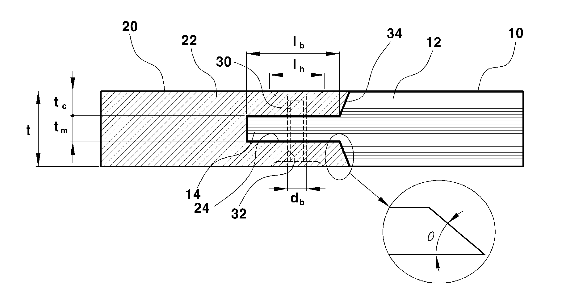
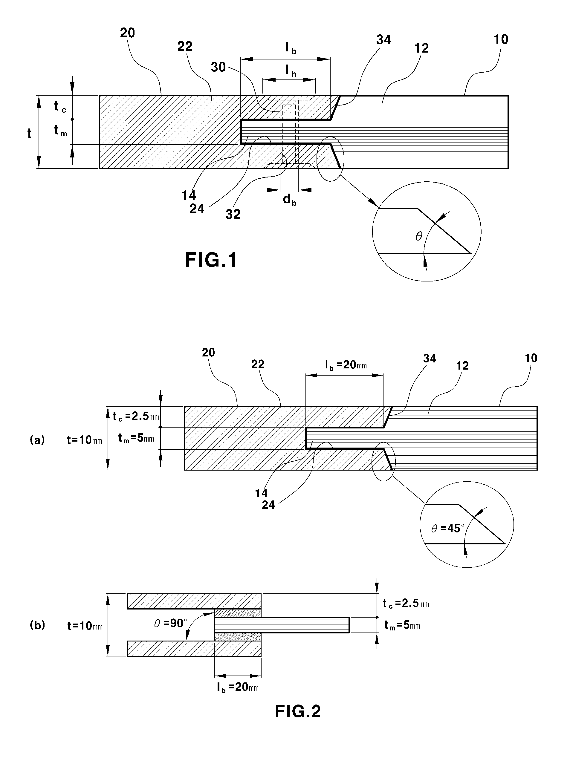
[0043]As described above, the fastening end 14 of the first joint end 12 of the carbon fiber / polymer composite 10 is primarily fitted in and fastened to the fastening slot 24 of the second joint end 22 of the metallic material 20 using an adhesive, and secondarily fastened to each other by using the female screw 30 and the male screw 32, in which as shown in FIG. 2a, the designed sizes for joint are as follow: t=10 mm, tm=5 mm, tc=2.5 mm, lb=20 mm, lh=0 mm, db=0 mm, and θ=45°


PUM

PropertyMeasurementUnit
Angleaaaaaaaaaa
Thicknessaaaaaaaaaa
Angleaaaaaaaaaa

Abstract

Disclosed is a device and method for joining a composite and a metallic material which can stably join a composite and a metallic plate while improving the joint strength thereof. The device includes a fastening end formed at the center of the end face of the first joint end of the composite to protrude integrally, and a fastening slot formed at the center of the end face of the second joint end of the metallic material. The fastening end of the composite is fitted and fastened in the fastening slot of the metallic material, a female screw is inserted along the thickness direction through the fitted and fastened part between the fastening end and the fastening slot, and a male screw is fitted in and fastened to the female screw.

Description

CROSS-REFERENCE TO RELATED APPLICATION[0001]This application claims under 35 U.S.C. §119(a) the benefit of Korean Patent Application No. 10-2011-0122703 filed on Nov. 23, 2011, the entire contents of which are incorporated herein by reference.BACKGROUND[0002](a) Technical Field[0003]The present invention relates to a device and method for joining a carbon fiber / polymer composite and a metallic material. More particularly, the present invention relates to a device and method for joining a carbon fiber / polymer composite and a metallic material which can stably join a carbon fiber / polymer composite and a metallic plate while improving the joint strength thereof.[0004](b) Background Art[0005]A conventional joint between a carbon fiber / polymer composite and a metallic material may be classified into i) single-lap joint, ii) double-lap joint, and iii) joint with attachments or the like in accordance with the shape of the joint. In such joints, an adhesively bonded joint method, and a hybr...

Claims


Application Information

Patent Timeline
IPC IPC(8): F16B11/00F16B17/00B32B37/12
CPCF16B5/02Y10T403/471B29C65/4835B29C65/5042B29C65/5057B29C65/562B29C65/564B29C65/72B29C66/1122B29C66/1142B29C66/12443B29C66/43B29C66/71B29C66/721B29C66/7212B29C66/742B29C66/72141F16B11/006Y10T403/7075B29K2307/04B29K2063/00F16B11/00B23P11/00B21D39/03
Inventor CHO, JEONG MINCHOI, YOUNG HO
Owner HYUNDAI MOTOR CO LTD
Learn More