
Display device

a display device and backlight technology, applied in the direction of identification means, electrical apparatus casings/cabinets/drawers, instruments, etc., can solve the problems of reducing the joint strength between the display module and the backlight module, increasing the risk of dust impurities and and increasing the probability of light leakage of the display module. , the probability of light leakage can be reduced, and the probability of dust entering or moisture entering the display device can be reduced.

Active Publication Date: 2021-08-31
AU OPTRONICS CORP
View PDF27 Cites 0 Cited by
  • Summary
  • Abstract
  • Description
  • Claims
  • Application Information

AI Technical Summary

Benefits of technology

This configuration improves the stability, display effect, and reliability of the device by enhancing module assembly integrity and reducing the thickness of the frame, facilitating the creation of narrow frame or frameless displays with improved user experience.

Problems solved by technology

However, when the frame is reduced or removed, assembly attachment areas of modules and assemblies of the display device might be reduced, thereby reducing joint strength between a display module and a backlight module, increasing a probability of light leakage of the display module, and increasing a risk that dust impurities and moisture enter the display device.
Therefore, when a narrow frame display device or even a frameless display device is developed, an unexpected defect may occur, thereby reducing quality of the display device.
These factors all restrict a degree for reducing or removing the frame of the display device, and therefore are not conducive to the development for a narrow frame display device or even a frameless display device.

Method used


Image

  • Display device
  • Display device
  • Display device

Examples


Embodiment Construction

[0013]Various embodiments are described below, and a person of ordinary skill in the art may readily understand the spirit and principle of the present invention with reference to the description in conjunction with accompanying drawings. However, although some particular embodiments are described in detail herein, these embodiments are merely used as examples, and in all aspects, these embodiments are not regarded as a limitative or exhaustive meaning. Therefore, for a person of ordinary skill in the art, various changes and modifications made to the present invention should be apparent and easy to achieve without departing from the spirit and principle of the present invention.

[0014]The thickness of a layer, a film, a panel, a region, and the like are amplified for clear description in the accompanying drawings. In the entire specification, same element symbols indicate same elements. It should be understood that, when an element such as a layer, a film, a region, or a substrate i...


PUM

PropertyMeasurementUnit
distanceaaaaaaaaaa
electricaaaaaaaaaa
elasticaaaaaaaaaa

Abstract

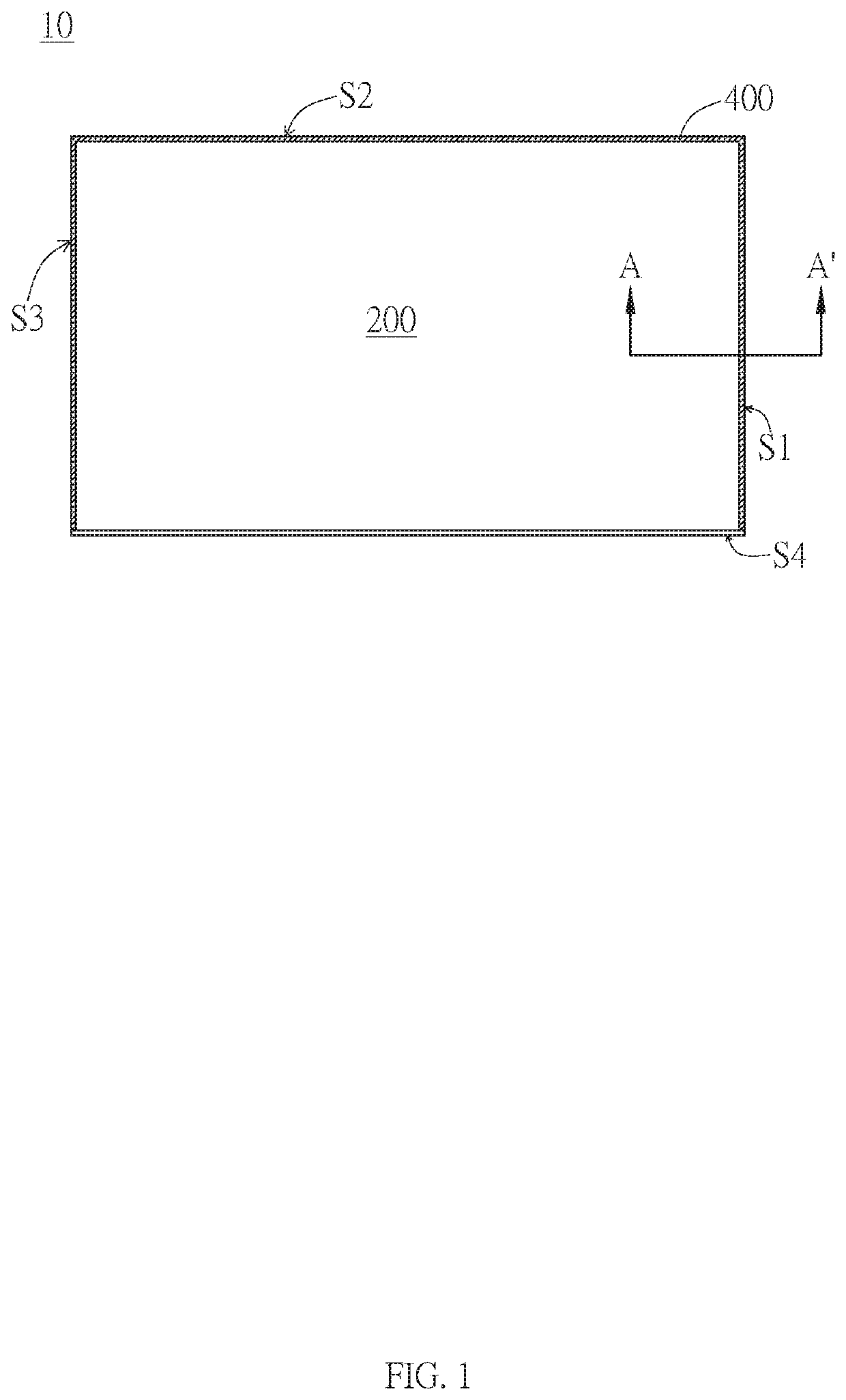
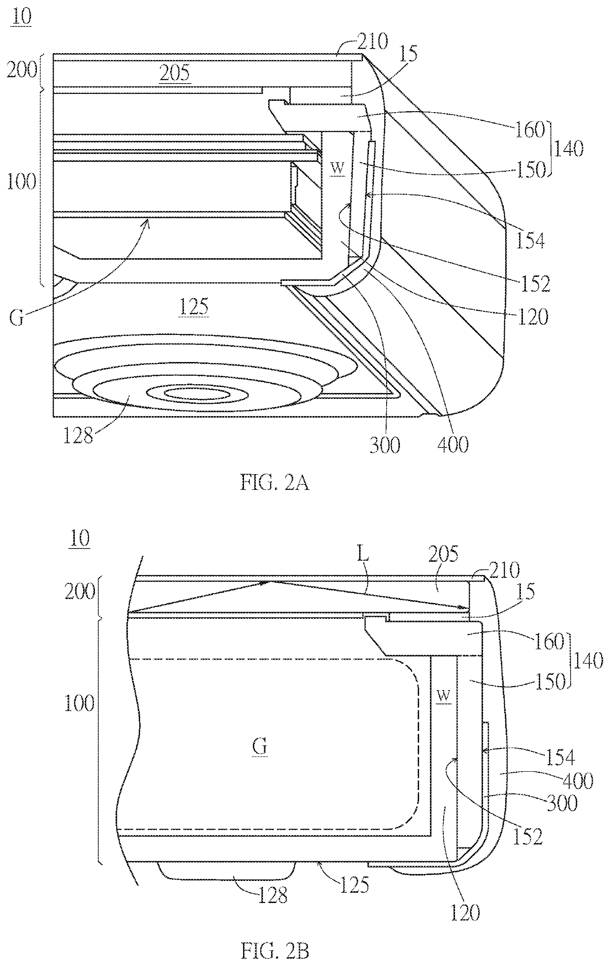
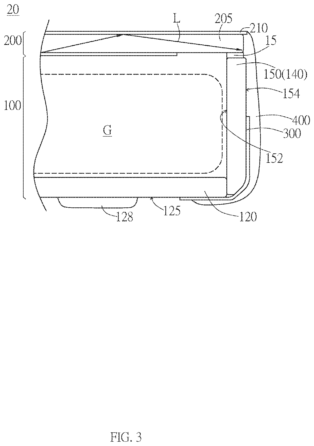
The present invention provides a display device including: a backlight module, including a back bezel having a bottom surface, and a frame having a side wall portion, where the side wall portion has an inner side surface and an outer side surface, and the back bezel faces the inner side surface of the side wall portion; a display module, disposed on the backlight module and supported by the frame; a tape, attached to the outer side surface of the side wall portion of the frame and extending to the bottom surface of the back bezel; and a sealant, disposed and extending from an end edge of the display module to the bottom surface of the back bezel through an outer side of the outer side surface of the side wall portion of the frame, and at least partially covering the tape.

Description

BACKGROUNDTechnical Field[0001]The present invention relates to a display device. Particularly, the present invention relates to a display device having a tape and a sealant.Related Art[0002]To improve a visual effect of a display device, a frame may be reduced or removed to implement a narrow frame display device or even a frameless display device. However, when the frame is reduced or removed, assembly attachment areas of modules and assemblies of the display device might be reduced, thereby reducing joint strength between a display module and a backlight module, increasing a probability of light leakage of the display module, and increasing a risk that dust impurities and moisture enter the display device. Therefore, when a narrow frame display device or even a frameless display device is developed, an unexpected defect may occur, thereby reducing quality of the display device. In addition, an assembly gap needs to be reserved for assembling the display device and other modules a...

Claims


Application Information

Patent Timeline
Patent Type & Authority Patents(United States)
IPC IPC(8): G06F1/16G02F1/1333G02F1/1335H05K5/00
CPCG06F1/1637G02F1/133308G02F1/133528G06F1/1656H05K5/0017G02F1/133311G02F1/133314G02F1/133317G09F9/30G02F2202/28G02F2201/08G06F1/1601
Inventor HUNG, PO-LANHUANG, YU-TSUNGSHEN, WEN-PINHSU, LI-CHIHWU, PEI-CHIAWANG, YEN-PO
Owner AU OPTRONICS CORP
Learn More