
Forward twisted profiled insulation for LAN cables

a profiled insulation and forward twisted technology, applied in the direction of insulating conductors/cables, cables, insulated conductors, etc., can solve the problems of dielectric materials having a negative impact on the electrical signal, contributing to signal loss, and other undesirable electrical phenomena, so as to maximize the distance between the conductors, minimize the amount of insulation used, and the effect of constant and stable design

Active Publication Date: 2013-05-23
BERK TEK
View PDF6 Cites 15 Cited by
  • Summary
  • Abstract
  • Description
  • Claims
  • Application Information

AI Technical Summary

Benefits of technology

The patent describes a way to make sure that a twisted pair of conductors has a consistent design along their length and uses the least amount of insulation possible. The insulation on the conductors is twisted to make the best contact between them, and a certain combination of insulation and polymer is used to prevent the peaks from getting crushed during the twisting process. This results in a twisted pair that is stable and secure, while also minimizing the use of insulation.

Problems solved by technology

Such signal degradation may be caused by factors such as interference with adjacent conductors, and inductance ith the insulation.
However, the dielectric material has a negative impact on the electrical signal and contributes to signal losses as well as other undesirable electrical phenomena.
In addition, this dielectric material adds cost to the cable construction and often has a negative impact on cable fire performance, such as in UL™ (Underwriters Laboratories) testing.
However, this method not only increases the complexity of the extrusion process, but often requires additional manufacturing equipment.
It is also difficult to manufacture a data communications cable with good electrical properties using this type of process.
However, prior art methods for producing such insulation with longitudinal air / gas openings require complex extrusion designs that may not produce the intended results or have otherwise produced ineffective results due to failure to maintain stable production of the openings during manufacturing.
This situation undesirably shortens the distance between the conductors negatively affecting impedance.
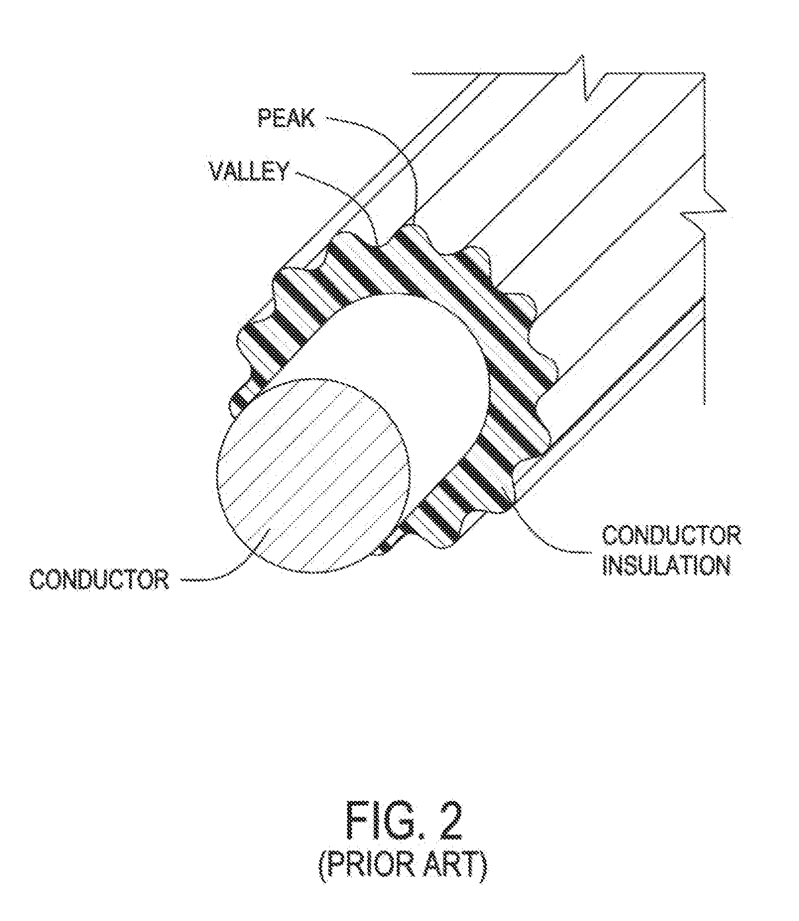
Moreover, if the nesting occurs periodically, the result is that along the pair at some points there is peak to peak contact and at other points there is peak to valley contact resulting in inconsistent impedance measurements along the length of the pair.

Method used


Image

  • Forward twisted profiled insulation for LAN cables
  • Forward twisted profiled insulation for LAN cables
  • Forward twisted profiled insulation for LAN cables

Examples


Embodiment Construction

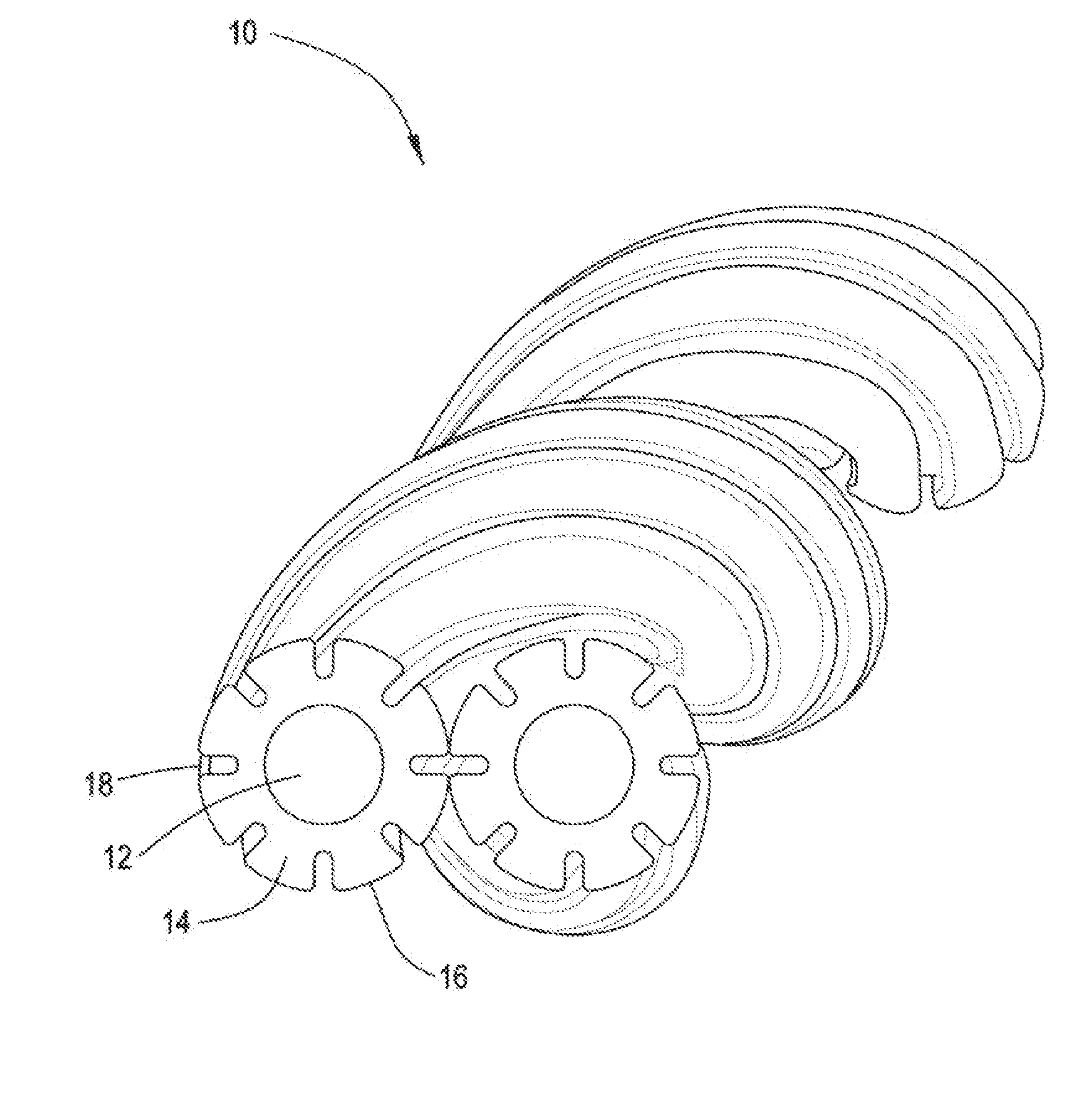
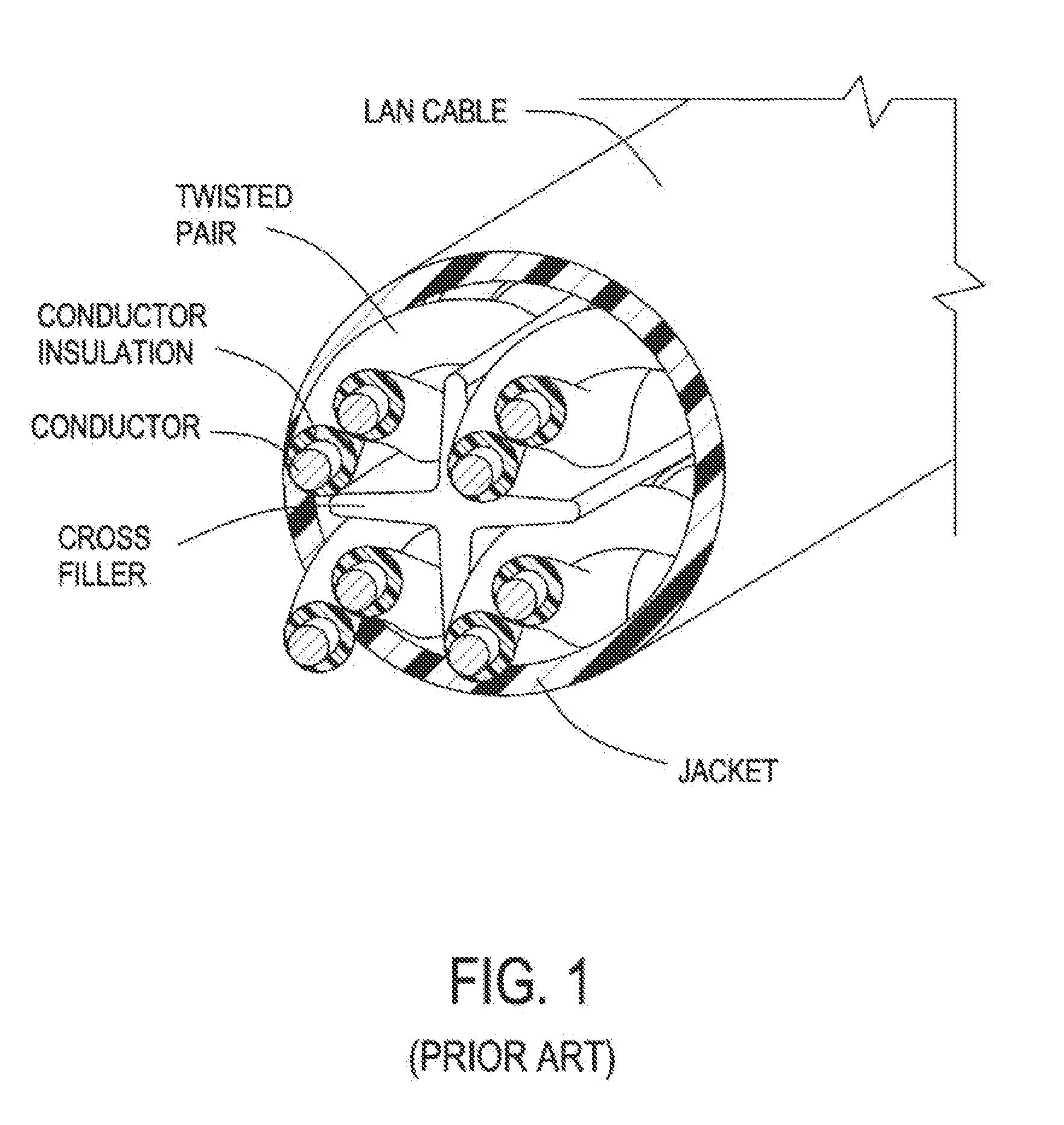
[0028]Applicants begin by providing a basic structure for a twisted pair 10 according to the present arrangement as shown in FIG. 5. Pair 10 has two conductors 12, each of which is surround by a profiled insulation 14, having successive peaks 16 and valleys 18. Such pairs are described throughout in the context of LAN type network communication cables, such as that shown in FIG. 1, however, the invention is not limited in that respect. The presently described pairs 10 may be used in any twisted pair arrangement, such as those found in large count network cables, telephone cables etc. . . . It is noted that FIG. 5 is solely to show the constituent parts of pair 10 and insulated conductors 12 / 14 irrespective of any forward twisting, which are discussed in more detail below.

[0029]The polymer used in profiled insulation 14 may be selected from fluorinated polymers such as (FEP) Fluorinated Ethylene Propylene, (PFA) Perfluoroalkoxy, (ETFE) Ethylene Tetrafluoroethylene, (PTFE) Polytetrafl...


PUM


Abstract

The present arrangement provides a twisted pair of conductors, each with a profiled insulation thereon, where in the twisted pair, the peak to peak contact of adjacent conductor insulation is ensured along the length of the pair. To this end, each of the profiled insulations on the conductors of the pair are forward twisted prior to twinning to ensure the maximum number of peak to peak contacts per unit length of the pair.

Description

BACKGROUND[0001]1. Field of the Invention[0002]This application relates to wire insulation. More particularly, this application relates to profiled insulation for LAN cables.[0003]2. Description of Related Art[0004]Copper cables are used for a variety of tasks, such as power transmission and signal transmission. In signal transmission tasks, the choice of insulation is of particular concern. For example, twisted pairs of copper conductors used in data cables (e.g. LAN (Local Area Network) cables) must meet certain fire safety standards and be cost effective, while minimizing signal degradation. Such signal degradation may be caused by factors such as interference with adjacent conductors, and inductance ith the insulation.[0005]Thus, in developing copper wire signal cables, often having multiple twisted pairs of copper wire within the same jacket, there are the competing concerns of minimizing cost while maximizing signal strength and clarity. FIG. 1 shows a common prior art design ...

Claims


Application Information

Patent Timeline
IPC IPC(8): H01B11/02
CPCH01B11/06H01B7/02H01B7/0275H01B7/184H01B7/185H01B7/189H01B11/02H01B11/18H01B13/14H01B13/143
Inventor HEFFNER, GREG
Owner BERK TEK
Learn More