
Counter electrode for dye-sensitized solar cell and preparation method thereof

a solar cell and counter electrode technology, applied in the field of counter electrodes for dye sensitized solar cells, can solve the problems of poor photoelectric efficiency of the solar cell, poor electrode property, and use of expensive tco electrodes, and achieve the effect of high photoelectric efficiency

Active Publication Date: 2013-05-23
KOREA INST OF SCI & TECH
View PDF7 Cites 58 Cited by
  • Summary
  • Abstract
  • Description
  • Claims
  • Application Information

AI Technical Summary

Benefits of technology

The patent presents a method to make a DSSC that is cheap and efficient at converting light to electricity. This is accomplished by using a specific type of electrodes called counter electrodes.

Problems solved by technology

However, these methods must use an expensive TCO electrode, and they need a vacuum process or a high temperature process.
Furthermore, when only the carbon-based material is used, there is a problem of that the photoelectric efficiency of the solar cell becomes inferior to the cell using the platinum.
Moreover, all of the processes must be carried out at low temperature in order to form the counter electrode directly on the flexible plastic substrate, and thus there is a problem of that the property of the electrode deteriorates.

Method used


Image

  • Counter electrode for dye-sensitized solar cell and preparation method thereof
  • Counter electrode for dye-sensitized solar cell and preparation method thereof
  • Counter electrode for dye-sensitized solar cell and preparation method thereof

Examples


example 1

Preparation of Photoelectrode

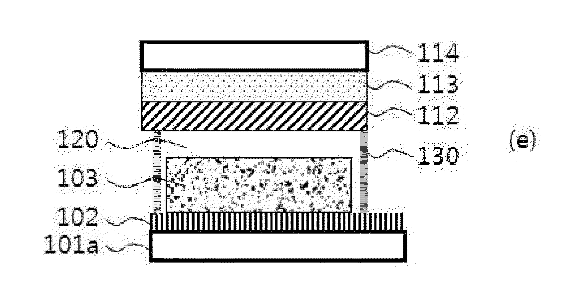
[0103]The glass substrate having conductivity (Philkington Co., material: FTO, thickness 2.2 cm, 8 Ω / sq, the substrate including 101a and 102 of FIG. 2) was prepared as the substrate for the photoelectrode. Successively, the porous membrane (thickness: 9 μn) including metal oxide nano-particles was formed thereon by coating metal oxide nano-particle paste including titanium oxide nano-particles (average particle diameter: 20 nm) 18.5 weight %, binder polymer (ethylcellulose) 0.05 weight %, and the residual quantity of solvent (terpineol) on the glass substrate (by using doctor blade method), and heat-treating the substrate at 500° C. for 30 minutes.

[0104]Continually, the photoelectrode was prepared by immersing the substrate in an ethanol solution including 0.5 mM photosensitive dye [Ru(4,4′-dicarboxy-2,2′-bipyridine)2(NCS)2] for 12 hours so that the photosensitive dye adsorbed to the surface of the porous membrane.

[0105](Preparation of Counter Electrode...

experimental example 1

[0117]Open-circuit voltage, photocurrent density, energy conversion efficiency, and fill factor of each dye-sensitized solar cell prepared in Example 1 and Comparative Example 1 were measured by the following method, and the results are listed in the following Table 1. Furthermore, the current-voltage curves of the DSSCs of Example 1 and Comparative Example 1 which were obtained in AM 1.5G 1 Sun condition were illustrated in FIG. 7 in comparison.

[0118](1) Open-Circuit Voltage (V) and Photocurrent Density (mA / cm2)

[0119]: Open-circuit voltage and photocurrent density were measured by using Keithley SMU2400.

[0120](2) Energy Conversion Efficiency (%), and Fill Factor (%)

[0121]: Energy conversion efficiency was measured by using a solar simulator (consisting of Xe lamp [1600W, YAMASHITA DENSO], AM1.5 filter, and Keithley SMU2400) of 1.5 AM 100 mW / cm2, and fill factor (FF) was calculated from the conversion efficiency according to the following Calculation Formula:

Fillfactor(%)=(J×V)maxJs...


PUM

PropertyMeasurementUnit
Temperatureaaaaaaaaaa
Timeaaaaaaaaaa

Abstract

The present invention relates to a counter electrode for DSSC which includes a porous membrane include a carbon-based material calcinated at high temperature and a platinum nano-particles and maintains higher conductivity than a thin membrane and in which the electrolyte moves smoothly, a method of preparing the same, and a DSSC using the same which is improved in photoelectric efficiency.

Description

CROSS-REFERENCE TO RELATED APPLICATION[0001]This application claims priority to and the benefit under 35 U.S.C. §119(a) of a Korean patent application No. 10-2011-0122385 filed on Nov. 22, 2011, the entire disclosure of which is incorporated herein by reference for all purposes.FIELD OF THE INVENTION[0002]The present invention relates to a counter electrode for dye-sensitized solar cell (hereinafter DSSC), a preparation method thereof, and a DSSC using the same.BACKGROUND OF THE INVENTION[0003]DSSC is represented by a photoelectrochemical solar cell announced by Gratzel et al., Switzerland, in 1991, and it is generally comprised of a photosensitive dye absorbing visible rays, metal oxide nano particles having wide band gap energy, a counter electrode which catalyses by platinum (Pt), and an electrolyte interposed between them. The DSSC has advantages of that the production cost is cheaper than existing silicon solar cells or compound semiconductor solar cells, the efficiency is high...

Claims


Application Information

Patent Timeline
IPC IPC(8): H01L31/0224B32B38/10
CPCY02E10/52Y02E10/542B32B37/025B32B2457/12G02B6/136H01G9/2022H01G9/2031H01G9/2059B32B2457/20H01L31/0224H01L31/04H01L31/18
Inventor KO, MIN-JAEYOO, KI-CHEONKIM, HONG-GONLEE, DOH-KWONKIM, BONG-SOOKIM, KYUNG-KON
Owner KOREA INST OF SCI & TECH
Learn More