Power supply wire for high-frequency current

Inactive Publication Date: 2013-05-16
KANZACC
View PDF9 Cites 5 Cited by
  • Summary
  • Abstract
  • Description
  • Claims
  • Application Information

AI Technical Summary

Benefits of technology

The power supply wire for high-frequency current described in the patent text has several technical effects. First, the wire bundle of each unit electric wire is composed of multiple conductive wires each individually coated with insulating films, which provides a wide surface area for the conductive wire and reduces the impact of the skin effect. Second, a gap is formed between the combined electric wire and the corrugated tube to relieve the pressing force and prevent deformation of the combined electric wire, which ultimately reduces heat generation. Third, the conductive wire bundle includes multiple conductive wire bundles, which reduces the alternating-current resistance in the high-frequency band and minimizes loss in device performance. Fourth, a spacer is provided to reduce vibrations and prevent damage to the combined electric wire during transportation or laying work and to prevent the connecting portion from disconnection. Fifth, the plurality of power supply wires for high-frequency current can be installed simultaneously. Lastly, the number of unit electric wires and other unit electric wires connected to individual terminals of the coil are equal, which prevents heat generation caused by eddy currents.

Problems solved by technology

However, when this electric wire is used as an electric wire for supplying a high-frequency current in a frequency range of 30 kHz to 100 kHz, a current density of a current flowing through the core wire is reduced due to a skin effect, and therefore power cannot be supplied efficiently.
The increase of the resistance may cause ignition.

Method used


Image

  • Power supply wire for high-frequency current
  • Power supply wire for high-frequency current
  • Power supply wire for high-frequency current

Examples


Embodiment Construction

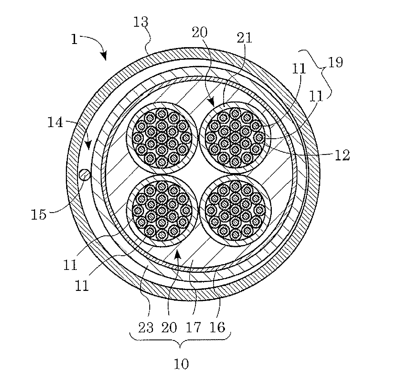
[0027]The preferred embodiments of the present invention will now be described with reference to FIG. 1 to FIG. 6 of the drawings. Identical elements in the figures are designated with the same reference numerals.

[0028]As illustrated in FIG. 1, a power supply wire 1 for high-frequency current of the present invention is configured by a corrugated tube 13 and a combined electric wire 10 disposed inside the corrugated tube 13.

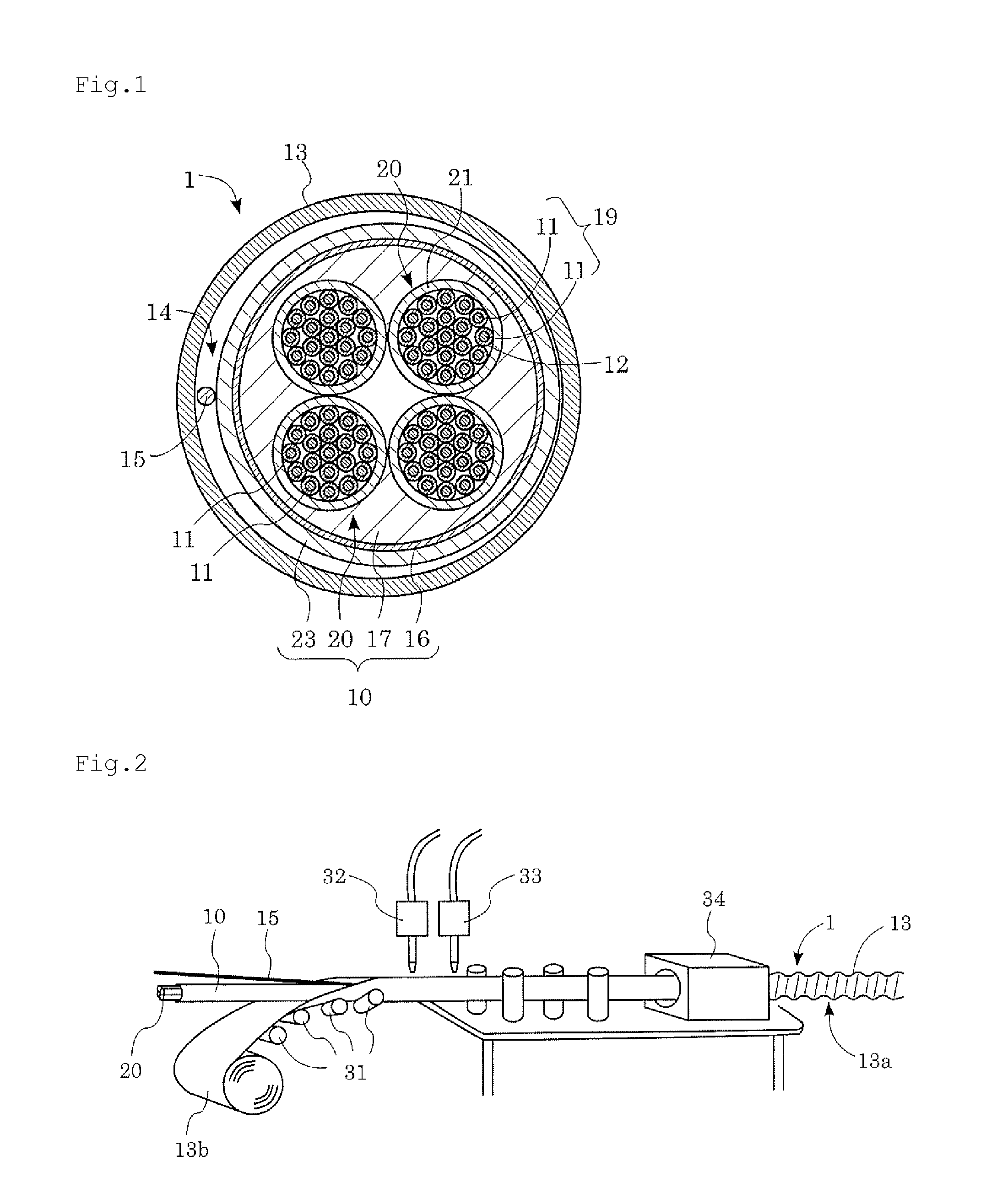
[0029]The corrugated tube 13 surrounds and thereby protects the combined electric wire 10, and is a tube made of metal such as aluminum, an aluminum alloy, copper, a copper alloy, stainless steel, or steel. A bent portion 13a (FIG. 2) in a corrugated form is formed in a length direction of the tube, and the bent portion 13a is spirally formed around the tube. To prevent the corrugated tube 13 from corroding, an anti-corroding layer made of a resin, coal tar, or the like may be formed on an outer circumference surface of the corrugated tube 13. Here, a size of the...


PUM


Abstract

There is provided a power supply wire for high-frequency current comprises: a corrugated tube made of metal; a combined electric wire disposed inside the corrugated tube and including a plurality of unit electric wires and a sheath material, each of the unit electric wires being formed by bundling together a plurality of conductive wires individually coated with insulating films, and the sheath material covering the plurality of unit electric wires; and a gap formed between the corrugated tube and the combined electric wire.

Description

BACKGROUND OF THE INVENTION[0001]1. Field of the Invention[0002]The present invention relates to a power supply wire for high-frequency current.[0003]2. Description of Related Art[0004]As a shielded electric wire, a wire disclosed in Japanese Unexamined Patent Application Publication No. 2007-305416 is proposed. This electric wire has an effect of shielding an electromagnetic wave from a core wire by surrounding an outer circumference surface of the core wire with a conductive corrugated tube. In addition, this electric wire can prevent damage of the core wire incurred from outside, and therefore can be used as an electric wire for supplying power.[0005]However, when this electric wire is used as an electric wire for supplying a high-frequency current in a frequency range of 30 kHz to 100 kHz, a current density of a current flowing through the core wire is reduced due to a skin effect, and therefore power cannot be supplied efficiently. Further, since the corrugated tube is filled w...

Claims


Application Information

Patent Timeline
IPC IPC(8): H01B9/02
CPCH01B9/02H01B7/16H01B7/303H01B7/1895
Inventor HIRAIKE, HIROSHIKONISHI, SHINJIRO
Owner KANZACC
Why Eureka
Try Eureka