
Solar tube panel with dual-exposure heat absorption

a technology of solar tube and heat absorption panel, which is applied in the safety of solar heat collectors, solar heat systems, lighting and heating apparatus, etc., can solve the problems of reducing the potential for tube failure and so as to reduce the temperature differential, and reduce the thermal stress in the tube

Inactive Publication Date: 2013-05-16
THE BABCOCK & WILCOX CO
View PDF9 Cites 10 Cited by
  • Summary
  • Abstract
  • Description
  • Claims
  • Application Information

AI Technical Summary

Benefits of technology

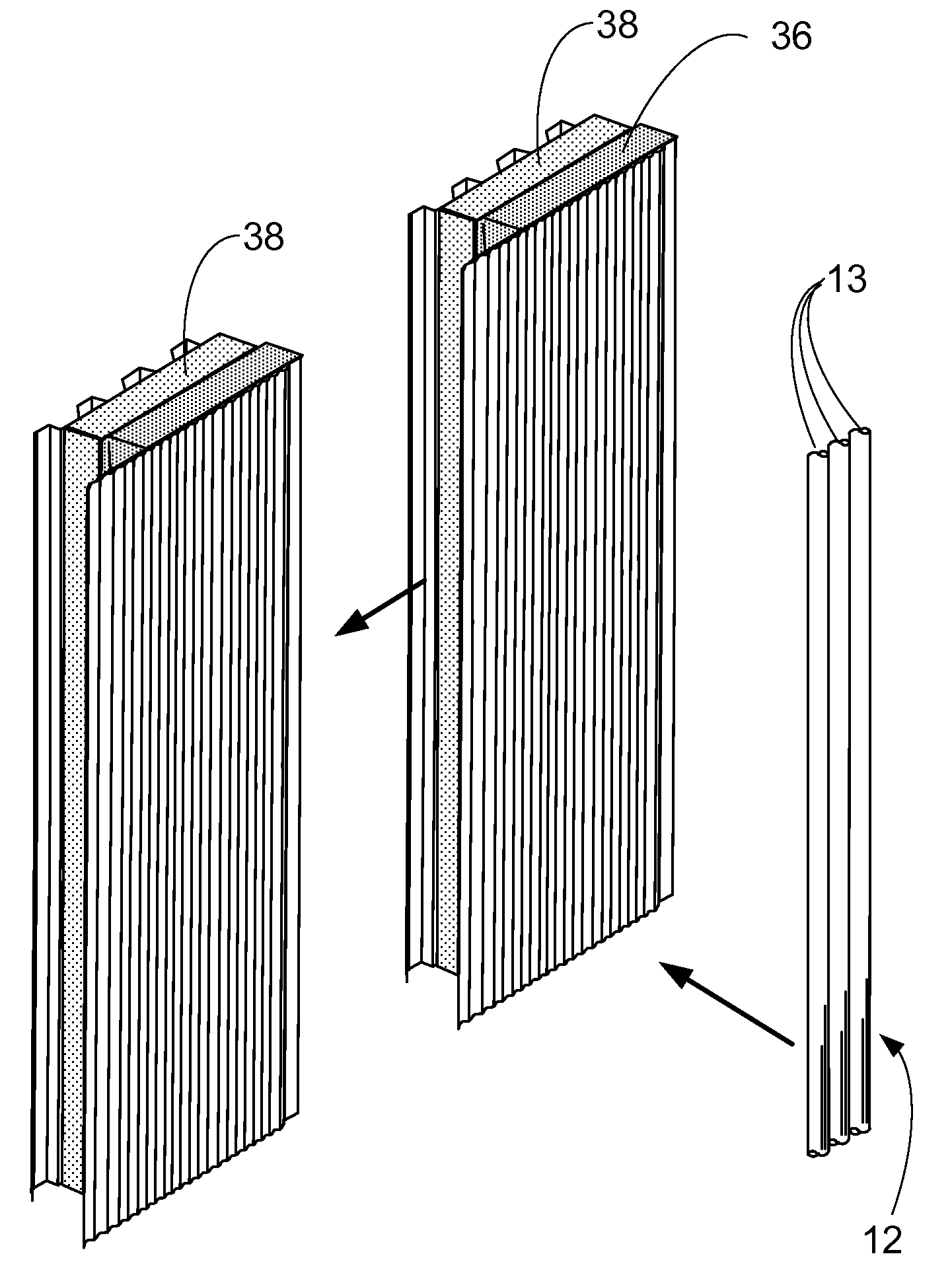
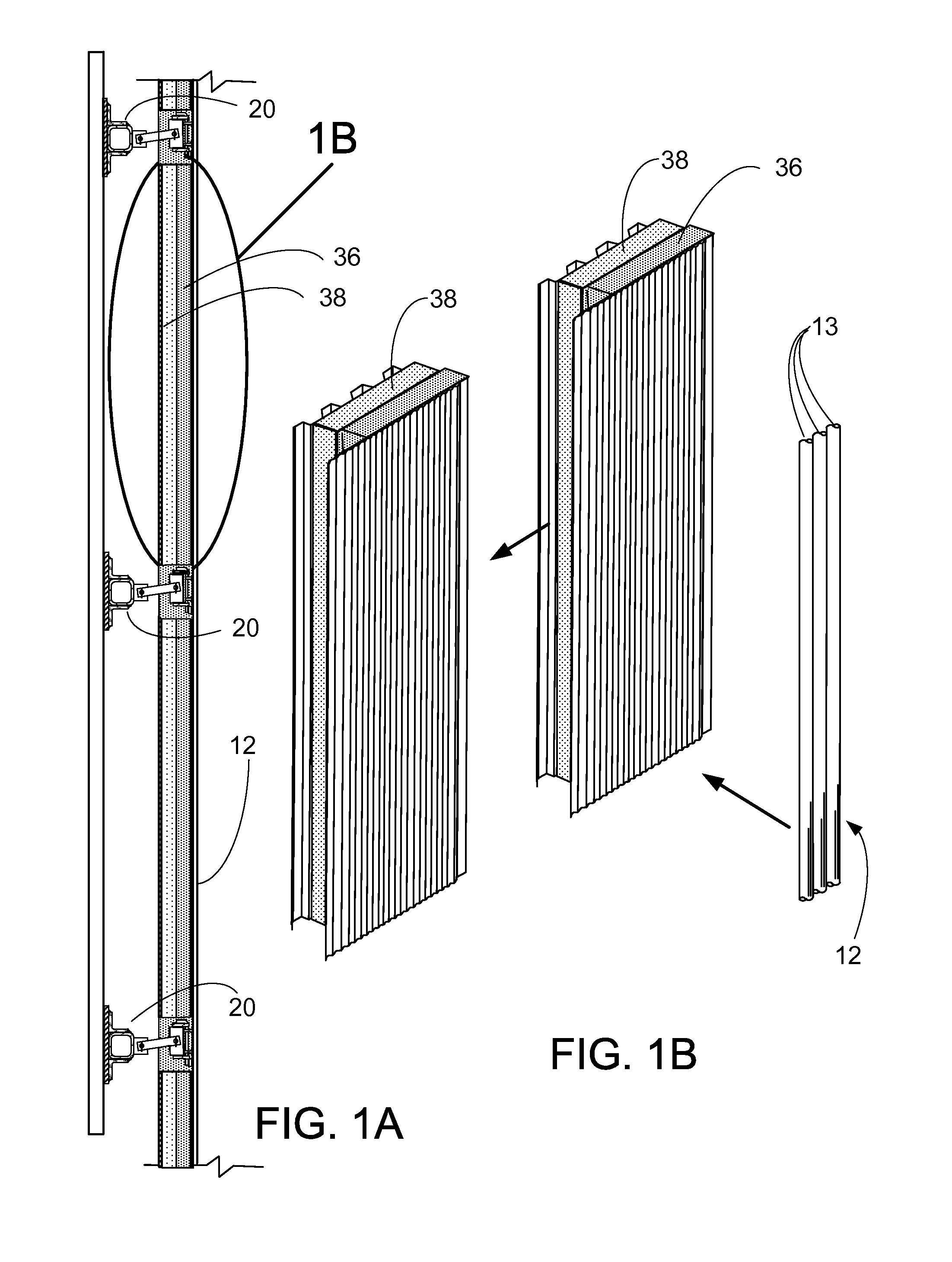
The present patent relates to heat absorbing tube panels that can absorb solar energy on two sides, resulting in more uniform tube temperature and reduced stress on the tube, which reduces the risk of failure. These panels can also absorb more solar energy, increasing efficiency. The patent also describes solar receivers that include heat transfer surfaces, a fluid system, a vertical support structure, and a stiffener structure. The technical effects of the patent include improved thermal performance and increased efficiency of heat absorbing panels and solar receivers.

Problems solved by technology

This results in significantly reduced thermal stresses in the tube and lower potential for tube failures.

Method used


Image

  • Solar tube panel with dual-exposure heat absorption
  • Solar tube panel with dual-exposure heat absorption
  • Solar tube panel with dual-exposure heat absorption

Examples


Embodiment Construction

[0042]A more complete understanding of the processes and apparatuses disclosed herein can be obtained by reference to the accompanying drawings. These figures are merely schematic representations based on convenience and the ease of demonstrating the existing art and / or the present development, and are, therefore, not intended to indicate relative size and dimensions of the assemblies or components thereof.

[0043]Although specific terms are used in the following description for the sake of clarity, these terms are intended to refer only to the particular structure of the embodiments selected for illustration in the drawings, and are not intended to define or limit the scope of the disclosure. In the drawings and the following description below, it is to be understood that like numeric designations refer to components of like function.

[0044]The modifier “about” used in connection with a quantity is inclusive of the stated value and has the meaning dictated by the context (for example,...


PUM


Abstract

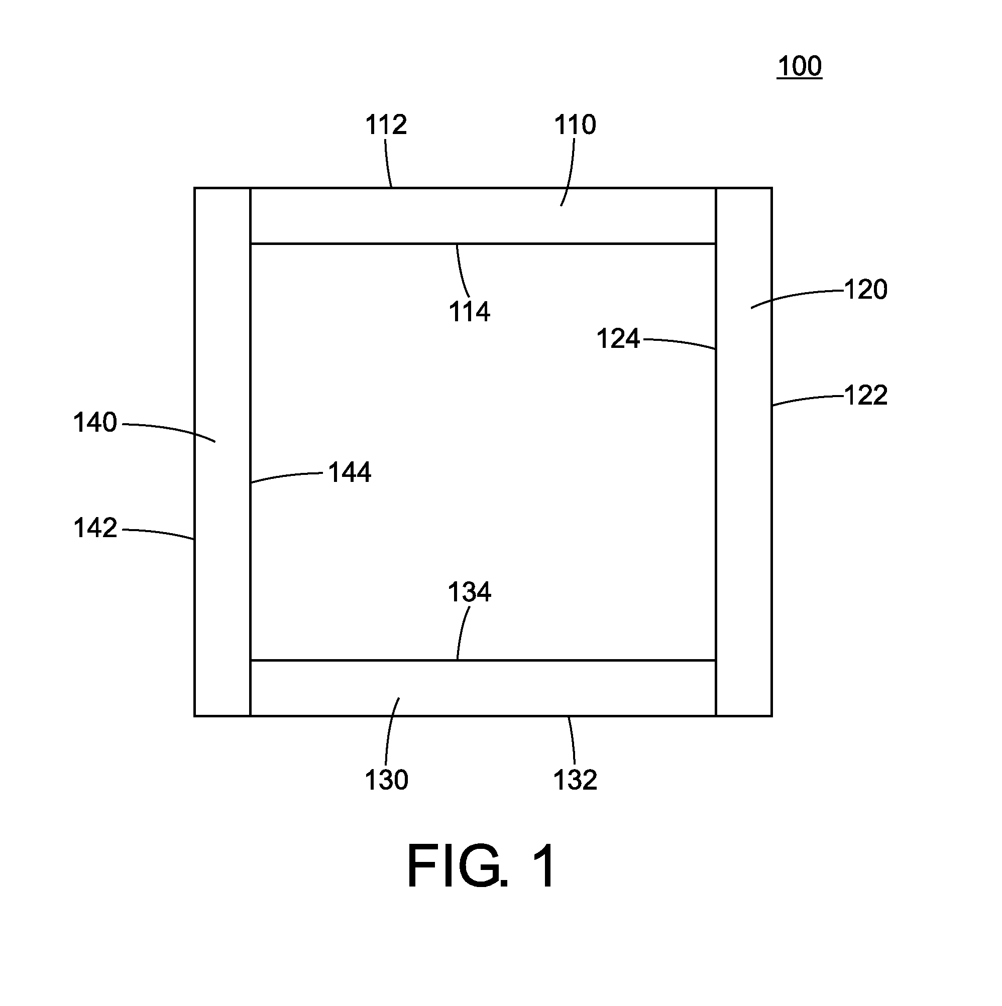
A dual-exposure heat absorption panel is disclosed, which can be used in a solar receiver design. Generally, the heat absorption panel includes a tube panel through which a heat transfer fluid is flowed to absorb solar energy from heliostats that are focused on the tube panel. A structural support frame surrounds the tube panel. A stiffener structure runs across the exposed faces of the tube panel. The headers and other support structures on the periphery are protected by use of a heat shield. Different tube couplings are possible with this structure, as well as different stiffening structures at the headers. The heat shield can be shaped to create an open space, permitting focusing of sunlight on the edge tubes as well. A curtain can be used as an additional heat shield in certain scenarios.

Description

BACKGROUND[0001]This application claims priority to U.S. Provisional Patent Application Ser. No. 61 / 560,527, filed on Nov. 16, 2011. The disclosure of this application is hereby fully incorporated herein by reference in its entirety.[0002]The present disclosure relates broadly to the field of solar power generation used to produce electricity. More particularly, this disclosure relates to a dual-exposure or two-sided heat absorption panel, and a solar receiver including one or more of such panels. These solar receiver designs can be used with Concentrated Solar Tower technology, also known as Concentrating Solar Power (CSP) technology to harness the sun's energy to produce “green” electricity.[0003]A solar receiver is a primary component of a solar energy generation system whereby sunlight is used as a heat source for the eventual production of superheated high quality steam that is used to turn a turbine generator, and ultimately produce electricity using the Rankine cycle or provi...

Claims


Application Information

Patent Timeline
Patent Type & Authority Applications(United States)
IPC IPC(8): F24J2/24F24S10/70F24S20/20
CPCF24J2/24F28F11/00F24J2/4623F24J2/07Y02E10/44F24J2002/4656Y02E10/41F24S2080/09F24S40/52F24S80/30F24S20/20F24S10/70Y02E10/40
Inventor KRAFT, DAVID L.WASLUK, DAVID T.PERSINGER, JUSIN A.MARSHALL, JASON M.
Owner THE BABCOCK & WILCOX CO
Learn More