
Transcatheter atrio-ventricular valve prosthesis

Active Publication Date: 2013-05-09
HIGHLIFE
View PDF3 Cites 50 Cited by
  • Summary
  • Abstract
  • Description
  • Claims
  • Application Information

AI Technical Summary

Benefits of technology

This patent is about a new heart valve replacement device that can be implanted using a catheter. The device has an inner part that is placed inside the heart and an outer part that surround it. This clamps the valve in place, providing a secure and effective replacement. The technical effects of this invention include improved heart valve replacement with a minimally invasive procedure that reduces the risk of complications for patients.

Problems solved by technology

As a result, there is abnormal leaking of blood from the left ventricle into the left atrium.
Nevertheless, predicting the outcome of percutaneous mitral balloon valvotomy remains somewhat limited.
Although there is some data comparing the outcomes of PBMV to surgical commissurotomy for patients with mitral stenosis, there is a paucity of data comparing the outcomes of PBMV to surgical mitral valve replacement.
In this case, a dilated left ventricle from ischemic or non-ischemic origin can result in mitral annular dilatation or a change in position of the papillary muscles and lead to abnormal closing of the mitral valve leaflets.
Mitral regurgitation is an important health problem.
Short- and long-term survival is worse when mitral regurgitation of any severity accompanies heart failure or a myocardial infarction.
Whether denying surgery in these patients was justified or not, the challenges of managing these patients will only increase in the coming years as the number of patients considered for surgery continues to rise.
Although surgical mitral valve repair and replacement can be associated with an acceptable mortality risk approaching 1% and 6%, respectively, it requires a sternotomy and cardiopulmonary bypass that can be associated with significant complications.
For repair of a degenerative mitral valve, failure to include an annuloplasty procedure negatively affects the long-term results of the procedure.
Furthermore, the respective role of mitral valve repair and replacement in this setting is also unclear.
Although mitral valve replacement with chordal preservation is associated with a higher operative mortality than mitral valve repair, replacement offers a significantly lower failure rate.
It can be hypothesized that the lack of mortality benefit associated with mitral valve repair is in some ways related to the poor durability results with mitral valve repair than mitral valve replacement.
However the atrio-ventricular heart valves do not offer a substantially cylindrical location like a vessel or an aortic or pulmonary valve.
Consequently anchoring by inner radial force is unstable.
Furthermore, the valve annulus usually is very supple and extends significantly under inner radial force which can be deleterious to the anchoring and to the heart function.
However, this technique will considerably impair atrial function, because atrial contraction is impeded.
While those authors describe means to achieve anchoring of a collapsible valve device, there is no clear description on how they achieve sealing contact to avoid peri-prosthetic leakages.
Quadri's device is anchored on the annulus and it does not reach inside the ventricle between the mitral leaflets but rather protrudes proximally inside the left atrium creating a no-flow zone and the risk of thrombus.
All of the devices described above share the same potentially unresolved issues.1. The mitral valve ring may give way to inner radial forces.2. The variations in ring shape and size may not be fitted for all prostheses.3. There could be mitral paravalvular regurgitation because the zone between the valve stent and the leaflet may not be sealed.4. An anchoring through the apex restricts the prosthesis to the use by surgeons and may compress the left ventricle in its cranial-caudal dimension.

Method used


Image

  • Transcatheter atrio-ventricular valve prosthesis
  • Transcatheter atrio-ventricular valve prosthesis
  • Transcatheter atrio-ventricular valve prosthesis

Examples


Embodiment Construction

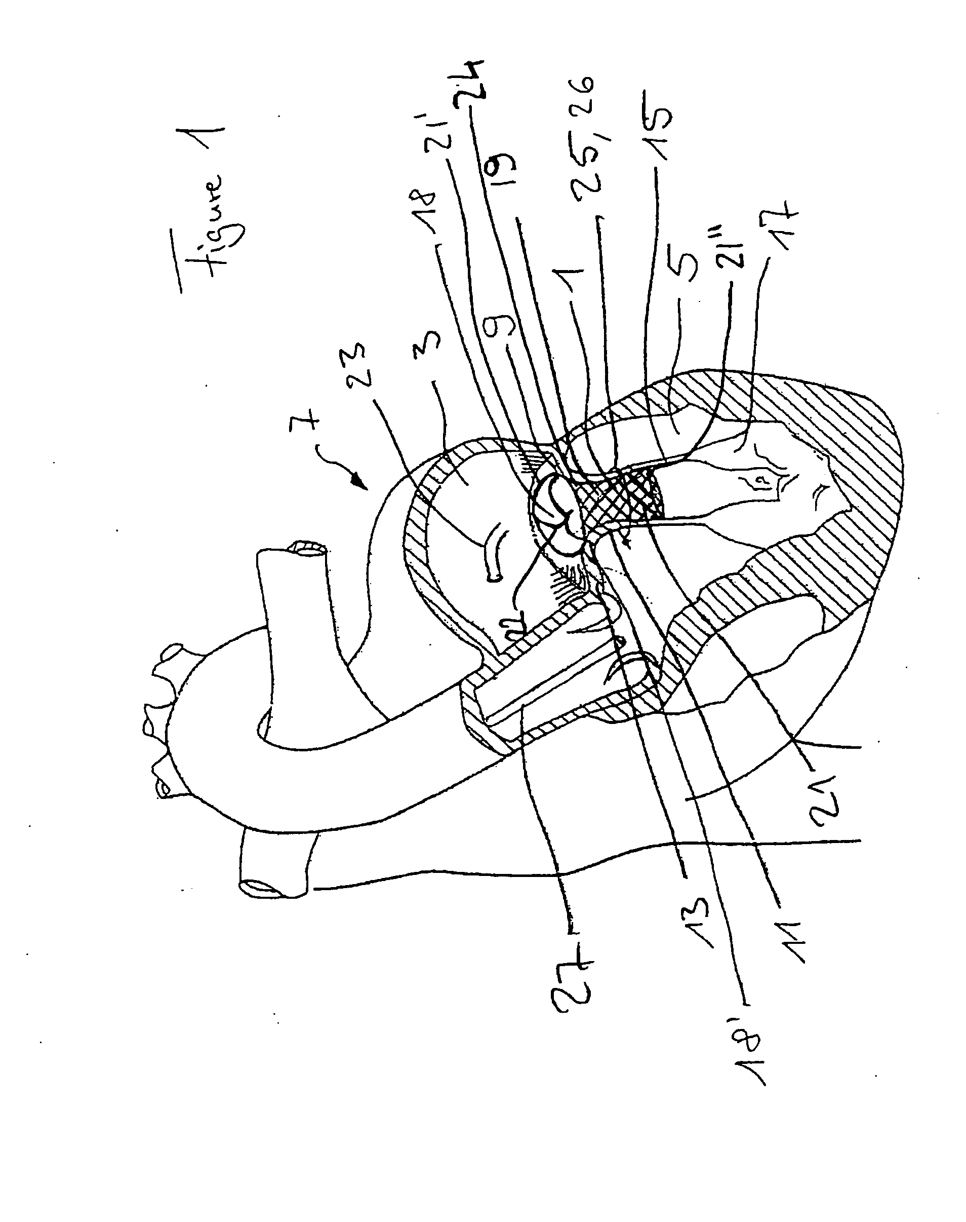
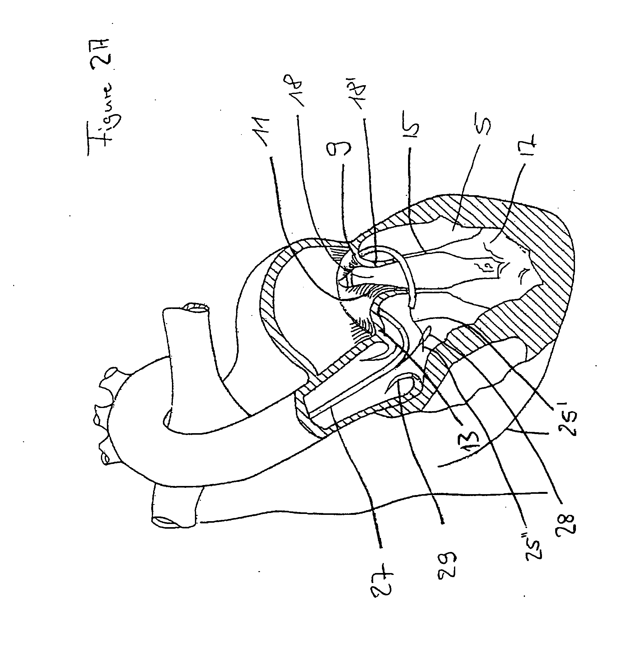
[0045]Implantation of a transcatheter atrio-ventricular valve prosthesis (mitral valve or tricuspid valve prosthesis) on a beating heart can be achieved by a minimally invasive approach in a mammal. This specification describes procedures and apparatuses, including the valve prosthesis itself, to insert and deploy the valve prosthesis and to anchor it by attachment to locations inside the heart.

[0046]According to an embodiment, the invention provides a transcatheter atrio-ventricular valve prosthesis. According to another embodiment, the invention provides a method for implanting a transcatheter atrio-ventricular valve prosthesis. Further embodiments of the invention are described below.

[0047]According to an embodiment of the invention, a transcatheter atrio-ventricular valve prosthesis for functional replacement of an atrio-ventricular valve in a connection channel, having a circumferential connection channel wall structure, between atrial and ventricular chambers of a heart is pro...


PUM


Abstract

A transcatheter atria-ventricular valve prosthesis for functional replacement of an atrio-ventricular valve in a connection channel, having a circumferential connection channel wall structure, between atrial and ventricular chambers of a heart, including an inner device to be disposed in the interior of the connection channel, the inner device having a circumferential support structure which is radially expandable and having a valve attached to the circumferential support structure, and an outer device to be disposed on the exterior of the connection channel, wherein the outer device at least partly extends around the inner device at a radial distance to the inner device, wherein the inner and outer devices form a securing mechanism for securing the circumferential connection channel wall structure therebetween.

Description

[0001]The present application claims priority and benefit of U.S. provisional application No. 61 / 363,070 and of German patent application No. 10 2010 036 824.5, the whole content of which applications is incorporated hereinto by reference.FIELD OF INVENTION[0002]The invention relates to atrio-ventricular valve (mitral valve or tricuspid valve) replacement devices for functionally replacing the corresponding native atrio-ventricular valve, and, in more detail, to a transcatheter atrio-ventricular valve replacement device or transcatheter atrio-ventricular valve prosthesis which allows implantation by means of a percutaneous approach, that is, a minimally invasive approach on a beating heart.Medical Background[0003]Normally the mitral valve allows blood to flow freely from the left atrial chamber to the left ventricular chamber during diastole when the heart is relaxed and prevents the backflow of blood from the left ventricle to the left atrium during systole when the heart contracts...

Claims


Application Information

Patent Timeline
IPC IPC(8): A61F2/24
CPCA61B17/064A61F2220/0066A61B17/1285A61B2017/003A61B2017/0403A61B2017/0427A61B2017/0464A61B2017/0475A61F2/2418A61F2/2457A61F2220/0008A61F2250/006A61F2/2475A61F2220/0016A61F2220/005A61B17/1227A61F2210/0057A61F2230/0067A61F2250/0063A61F2/2454A61F2/2442A61F2230/0091A61F2250/007A61F2250/0069A61F2/2409A61F2250/001A61F2/2427
Inventor WEBER, JOSEF
Owner HIGHLIFE
Learn More