Method for producing fuel cell catalyst, fuel cell catalyst, and uses thereof
- Summary
- Abstract
- Description
- Claims
- Application Information
AI Technical Summary
Benefits of technology
Problems solved by technology
Method used
Image

Examples
example 1
1. Preparation of the Fuel Cell Catalyst
[0080]5.88 g (56 mmol) of carbonized niobium (NbC, manufactured by Soekawa Chemical Co., Ltd.), 0.87 g (5 mmol) of ferric acetate (Fe(CH3CO2)2, manufactured by ALDRICH), and 5.14 g (48 mmol) of nitrified niobium (NbN, manufactured by Kojundo Chemical Laboratory Co., Ltd.) were thoroughly mixed. The resultant mixed powder was heated in a tubular furnace under a nitrogen atmosphere at 1,600° C. for three hours. Thereby, 10.89 g of an iron and niobium carbonitride (1) was obtained. The obtained carbonitride (1) was a sintered body and, thus, was ground using a mortar.
[0081]1.18 g of an iron and niobium oxycarbonitride (1) was obtained by heating 1.05 g of the obtained powdered carbonitride (1) in a rotary kiln at 900° C. for seven hours under a flow of a nitrogen gas comprising 0.75% by volume of oxygen gas and 4% by volume of hydrogen gas.
[0082]The iron and niobium oxycarbonitride (1) was milled using a planetary ball mill (Premium 7, manufactur...
example 2
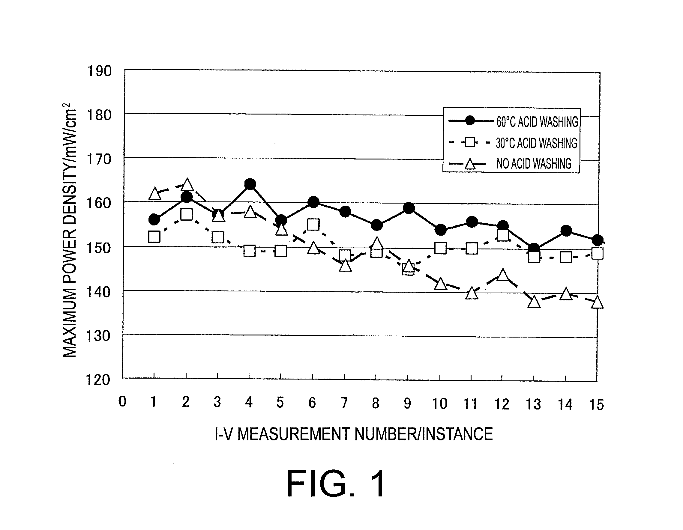
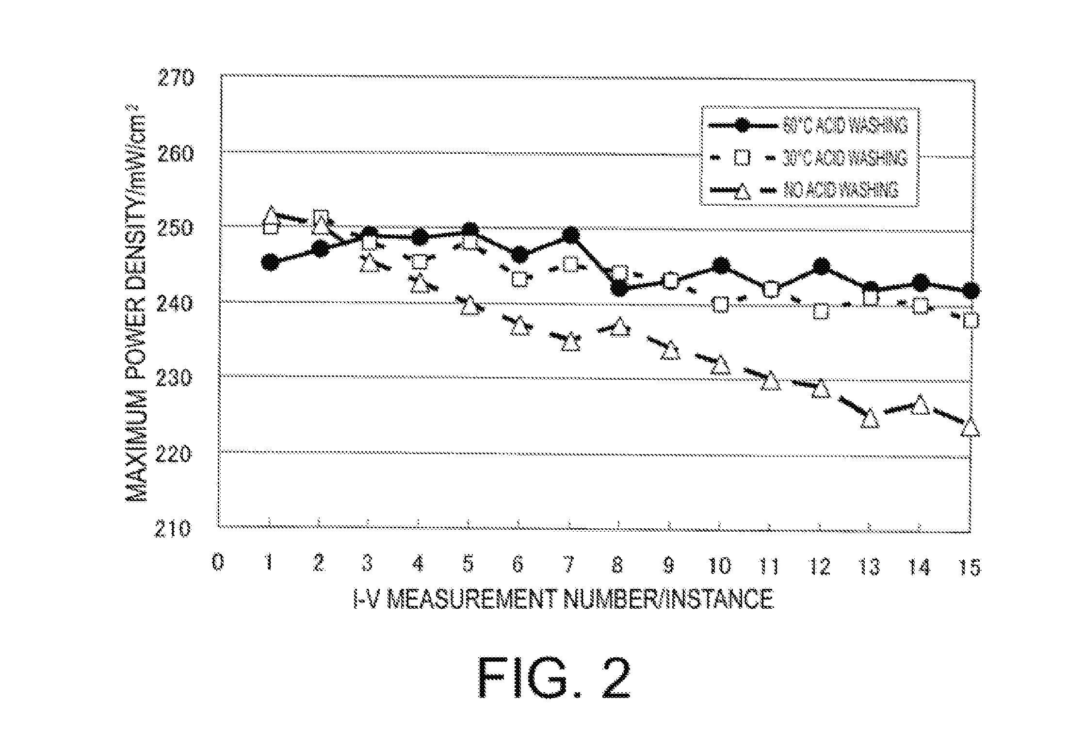
[0100]Aside from adding 0.35 g of the fuel cell catalyst (1) to 350 mL of 1N sulfuric acid and then agitating for 144 hours while maintaining the temperature of the solution at 60° C., a fuel cell catalyst (3) was fabricated in the same manner described in “1. Preparation of fuel cell catalyst” in Example 1.
[0101]Dissolved metal content of the fuel cell catalyst (3) is shown in Table 1.
[0102]Next, aside from using the fuel cell catalyst (3) in place of the fuel cell catalyst (2), a single cell of a polymer electrolyte fuel cell (hereinafter referred to as “single cell (2)”) was fabricated in the same manner described in Example 1. Note that an MEA that was used for fabricating the single cell (2) is referred to as “MEA (2)”.
Evaluation of Power Generation Property (Measurement of Catalytic Performance)
[0103]Slope of the approximation formula of MEA (2) measurement number vs. the maximum power density was −0.50.
example 3
1. Preparation of the Fuel Cell Catalyst:
[0104]4 g (50 mmol) of titanium oxide (TiO2), 1.5 g (125 mmol) of carbon black (XC-72, manufactured by Cabot Corporation), and 0.16 g (0.5 mmol) of lanthanum oxide (La2O3) were thoroughly mixed. 2.7 g of a titanium and lanthanum carbonitride (2) was obtained by heating the resultant mixture at 1,700° C. for three hours in a nitrogen atmosphere. The obtained carbonitride (2) was a sintered body and, thus, was ground using a mortar.
[0105]1.18 g of a titanium and lanthanum oxycarbonitride (2) was obtained by heating 1.0 g of the obtained powdered carbonitride (2) at 900° C. for four hours in a tubular furnace under a flow of a nitrogen gas comprising 1% by volume of oxygen gas and 1% by volume of hydrogen gas.
[0106]This titanium and lanthanum oxycarbonitride (2) was pulverized in the same manner described in “1. Preparation of fuel cell catalyst” in Example 1 in order to obtain a fuel cell catalyst (4).
[0107]Thereafter, 0.35 g of the fuel cell c...
PUM
| Property | Measurement | Unit |
|---|---|---|
| Temperature | aaaaa | aaaaa |
| Temperature | aaaaa | aaaaa |
| Time | aaaaa | aaaaa |
Abstract
Description
Claims
Application Information
 - R&D
- Intellectual Property
- Life Sciences
- Materials
- Tech Scout
- Unparalleled Data Quality
- Higher Quality Content
- 60% Fewer Hallucinations
Browse by: Latest US Patents, China's latest patents, Technical Efficacy Thesaurus, Application Domain, Technology Topic, Popular Technical Reports.
© 2025 PatSnap. All rights reserved.Legal|Privacy policy|Modern Slavery Act Transparency Statement|Sitemap|About US| Contact US: help@patsnap.com