
Monofilament-Reinforced Hollow Fiber Membrane with Scalloped Lumen

a hollow fiber membrane and monofilament technology, applied in the field of macroscopy composite hollow fiber membranes, can solve the problems of poor permeation efficiency, lack of useful knowledge in avoiding damage to the membrane or maximizing permeation efficiency of the reinforced membrane, and poor performance of the reinforced membrane. , to achieve the effect of superior braided membran

Active Publication Date: 2013-05-09
LOTTE CHEM CORP
View PDF12 Cites 5 Cited by
  • Summary
  • Abstract
  • Description
  • Claims
  • Application Information

AI Technical Summary

Benefits of technology

The patent describes a process for making a membrane with a hollow fiber asymmetric microporous membrane. The membrane has a relatively thick wall of polymer film, with a monolayer of monofilaments embedded near the lumen. The monolayer provides better filtration into the lumen than braids made with multifilament yarn. The membrane has an adhesive strength, bubble point, and percent rejection of polystyrene bead within certain ranges. The process involves weaving an open tubular braid over a core cable, coating it with a membrane-forming dope, and coagulating it to form a semipermeable thin polymer film. The membrane is then washed and dried. The technical effect of this patent is to provide a membrane with improved filtration and separation capabilities.

Problems solved by technology

Damage to a single membrane in a module, which damage results in dirty water contaminating the permeate, is a serious problem which occurs more often than desired.
To date, numerous braided membranes have been disclosed, each of which purports to provide desirable filtration efficiency but offer scant useful knowledge relating to avoiding the damage to a membrane or maximizing permeate efficiency.
The stabilizing effect of the openings in the reinforcing material was lost (see sentence beginning at the bottom of col 4, and bridging cols 4 and 5) when the braid was coated with polymer, so that their reinforced membrane was not an effective membrane.
Thus, it was not known how embedding the braid in the film affected the performance of the membrane; nor was it established whether failing to embed the braid in the film provided a significant advantage.
However, when the braid is coated with a relatively elastic polymer to form the membrane, it is essentially longitudinally non-extensible (along the z-axis).
The non-embedded yarn, in all such instances, is prone to damage such as pin-holes.
Further, the importance of stability of the structure of the braid during operation, particularly the effect of shrinkage, was not known.

Method used


Image

  • Monofilament-Reinforced Hollow Fiber Membrane with Scalloped Lumen
  • Monofilament-Reinforced Hollow Fiber Membrane with Scalloped Lumen
  • Monofilament-Reinforced Hollow Fiber Membrane with Scalloped Lumen

Examples


example 1

[0094]Duplication of feeding a monofilament braid as described in the Yoon et al publication No. US 2009 / 0206026:

[0095]A monofilament braid of 100 denier (0.1 mm) nylon monofilament was spirally woven on a 1.0 mm cable of metal wire, alternate filaments being woven at opposed spiral angles of 30°. The sheathed cable was placed on a 2.54 cm diameter rubber roller rotating at 30 rpm. The braid was crumpled on the cable and could not be advanced. The speed of the roller was reduced to 15 and then 5 rpm. In no case was the braid advanced without damage. The roller speed was then increased to 40 rpm. The braid was crumpled.

example 2

[0096]The following three grades of PVA available from Kuraray were each melt extruded in a single screw Hankook Model M-65 extruder fitted with a 65 mm diameter screw having a length / diameter ratio of 22. The barrel temperature is 195° C. and the die temperature 160° C. The die is provided with 18 scalloped through-apertures (holes) and the average diameter of each aperture is 1.6 mm. The air quenching length for the PVA cable is 2 m in 25° C. air for 2 seconds. The drawing ratio is 1.5:1.

Extrusion Temp 195° C.Fully hydrolyzed (F-05 and F-17)degradesIntermediate hydrolyzed (M-17)degradesPartially hydrolyzed (P-24, P-20,degradesP-17 and P-05)

example 3

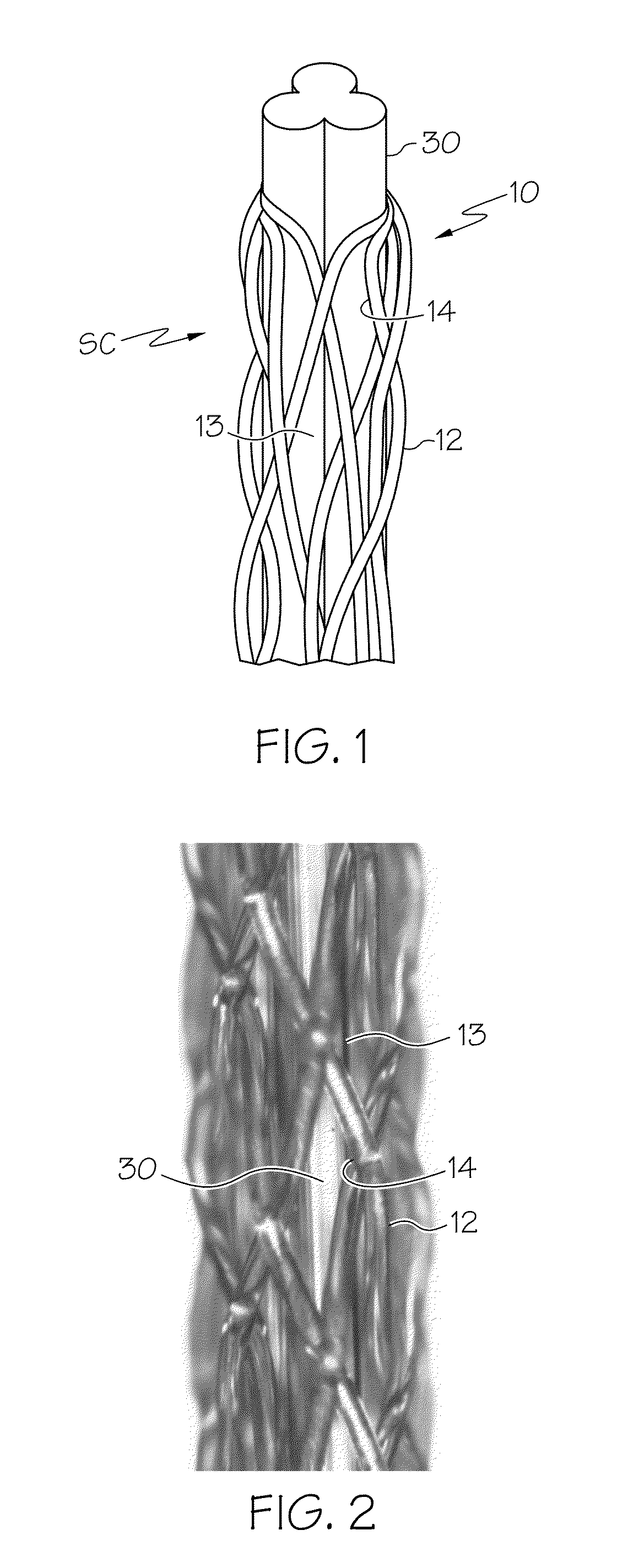
[0097]A braid is formed by weaving 12 filaments, each of 100 denier nylon, at a spiral angle of 35° over a plasticized PVA cable having a diameter of 0.75 mm using a custom-built braiding machine. The sheathed cable is pulled through a coating nozzle into which a dope, prepared as described above to have a viscosity of 43,000 cps at 30° C., is flowed at an output rate of 11 g / min. The dope infiltrates the braid, coats the cable and embeds the braid. The membrane is coagulated in a water bath at 45° C. and washed as shown in FIG. 5. The wall thickness of the membrane is 400 μm the braided monofilaments forming a monolayer around the lumen which has essentially a little larger diameter than that of the dissolved cable, namely 0.8 mm, because PVA cable is swollen in the coagulation bath and cleaning bath before the membrane finishes its coagulation. The cross-section of the braid is schematically illustrated in FIG. 3.

[0098]The physical properties of the membrane made in Example 3 abov...


PUM

PropertyMeasurementUnit
temperatureaaaaaaaaaa
lumen diameteraaaaaaaaaa
inner diameteraaaaaaaaaa

Abstract

A hollow fiber membrane is formed by embedding a braid having a spiral open weave of monofilaments only, to avoid a “whiskering” problem. The open weave is characterized by contiguous, circumferential, rhomboid-shaped areas of polymer film separated by monofilaments. When the braid is supported on a plasticized PVA cable having a scalloped periphery, the braid can be infiltrated with membrane polymer which, when coagulated, embeds the braid positioning it around the lumen.The embedded spiral weave, free of any circumferentially constricting monofilament, allows the membrane to be biaxially distensible. The membrane has “give” not only in the axial or longitudinal direction but also in the radial direction. “Give” in the radial direction permits soiled membranes to be backwashed under higher pressure than in a comparable braid which is not radially distensible.

Description

CROSS-REFERENCE TO RELATED APPLICATION[0001]This application is a continuation-in-part application of Ser. No. 13 / 338,557 filed 28 Dec. 2011.FIELD OF THE INVENTION[0002]This invention relates to a macroscopic composite hollow fiber membrane which is reinforced with multiple multifilament yarns braided into a tubular shape; each such yarn is made by plaiting or twisting multiple strands or monofilaments of a polymer having desired tensile strength. The tubular braid is then coated with a membrane-forming dope (polymer solution or “dope” for brevity) which is coagulated to form a tubular polymer membrane having a lumen diameter of at least 0.5 mm. Such construction is designed for use in demanding applications in which permeate is required to meet strict specifications. For example, for water filtration, one or more skeins are used, each skein comprising a multiplicity of hollow fiber membranes (hereafter “fibers” or “membranes” for brevity) in a module which is deployed in a reservoi...

Claims


Application Information

Patent Timeline
Patent Type & Authority Applications(United States)
IPC IPC(8): B01D69/08D06B1/02D06B21/00D04C1/06
CPCB01D69/08B01D69/082D06B1/02D06B21/00B29K2469/00B29K2227/06B29K2267/00B29K2269/00B29K2427/16B29K2431/04B29K2631/04B29K2669/00B29K2827/16B29K2233/08B29K2225/06B01D61/145B01D61/147B01D69/087B01D71/34B29K2027/16B29K2031/04B29K2069/00B29C70/222B29K2309/08B29K2869/00B01D2323/42B01D2325/40B29K2277/00B29K2831/04B29K2231/04B29K2627/16B29K2227/16D04C1/06B01D69/02B01D2325/24B01D61/14D04B1/22B01D67/00
Inventor SEO, CHANG MINLEE, GYEONG MO
Owner LOTTE CHEM CORP
Learn More