
Apparatus for deburring workpiece

a technology for deburring workpieces and workpieces, which is applied in the direction of grinding drives, grinding machine components, manufacturing tools, etc., can solve the problems of increasing the time and cost of manufacturing a finished product, causing the most manufacturing cost, and difficult mechanical design of the automation arrangement to remove burrs, so as to minimize the contamination of a working place

Active Publication Date: 2013-04-25
KOREA AEROSPACE INDUSTRIES
View PDF17 Cites 45 Cited by
  • Summary
  • Abstract
  • Description
  • Claims
  • Application Information

AI Technical Summary

Benefits of technology

The present invention provides a deburring apparatus that can quickly and efficiently remove burrs from metallic and non-metallic products during the deburring process. The apparatus includes a transfer module for transferring the workpiece to be deburred, a deburring module for deburring the workpiece, and a blocking cover for selectively preventing the transfer module and the workpiece from being exposed to outside, and minimizing noise and dust produced during the process. The apparatus can also quickly discharge foreign matters produced during the process, keeping the working space clean and improving the continuity of the deburring work.

Problems solved by technology

In addition, in a case that an automation arrangement has a very complex internal shape, the mechanical design of the automation arrangement to remove burrs is very difficult.
However, a scheme to manually remove the burrs may increase the time and cost to manufacture a finished product.
In addition, since the automation arrangement to remove burrs is not provided, most manufacturing cost is caused by the manual work of removing the burrs, and the quality of the manufactured product is not uniform.
However, this cannot actually make many difficulties.

Method used


Image

  • Apparatus for deburring workpiece
  • Apparatus for deburring workpiece
  • Apparatus for deburring workpiece

Examples


Embodiment Construction

[0028]Hereinafter, exemplary embodiments of the present invention will be described in more detail with respect to accompanying drawings. However, the present invention is not limited to following disclosed embodiments, but can be realized as various modifications. The present embodiments make the disclosure of the present invention perfect, and provided for illustrative purposes, so that those skilled in the art can perfectly comprehend the scope and the spirit of the present invention. The same reference numbers will be assigned to the same elements in the accompanying drawings.

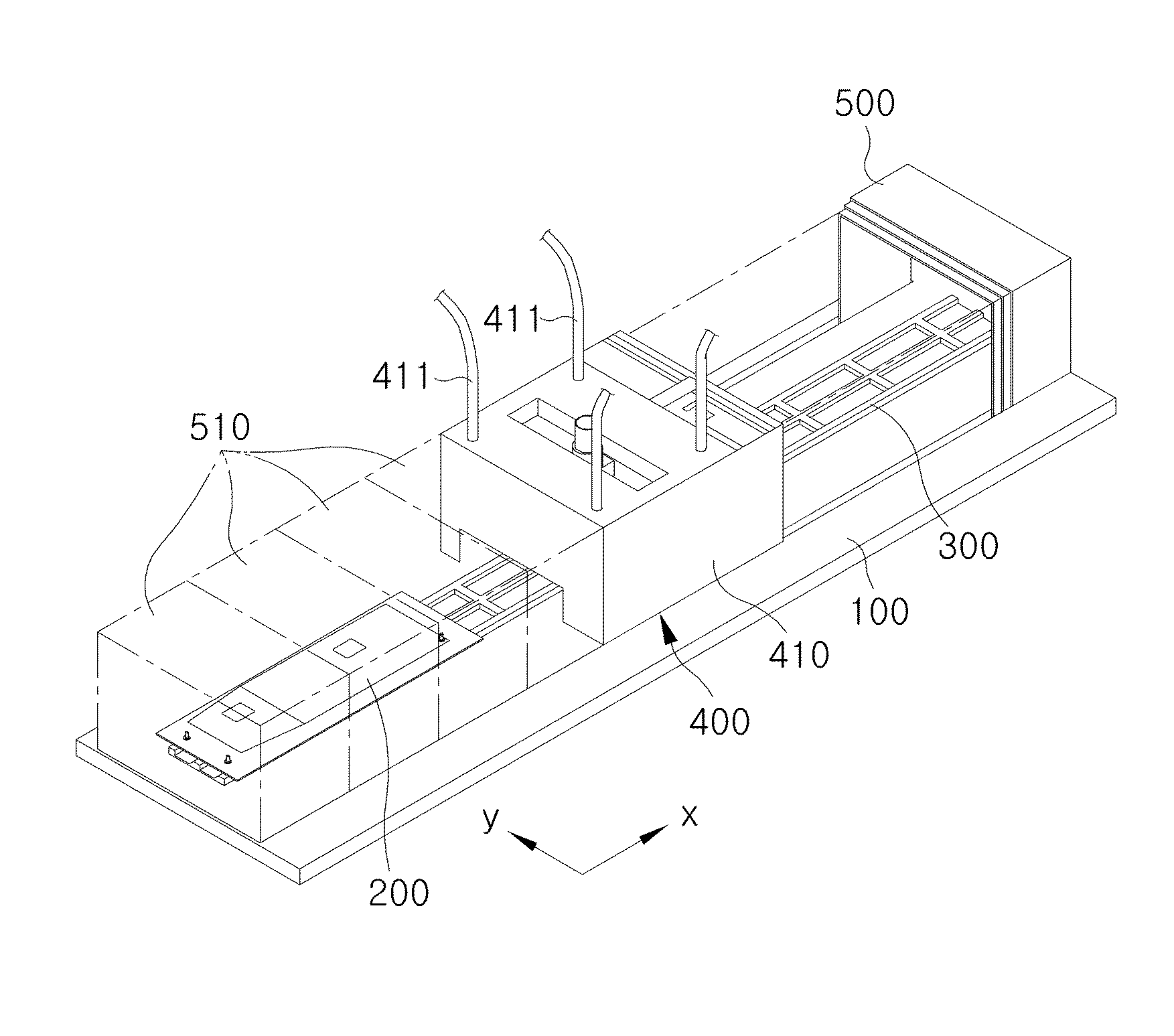
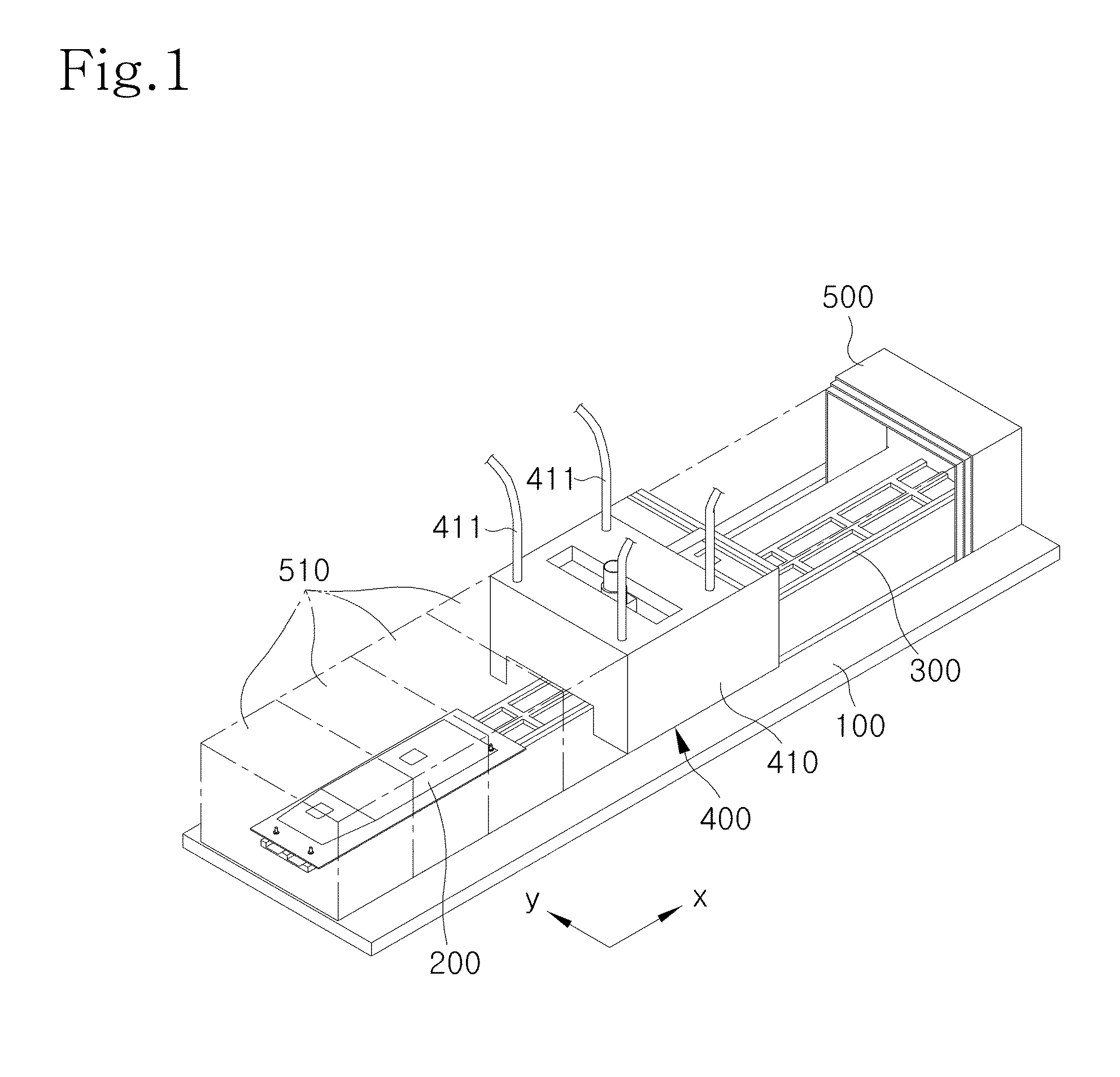
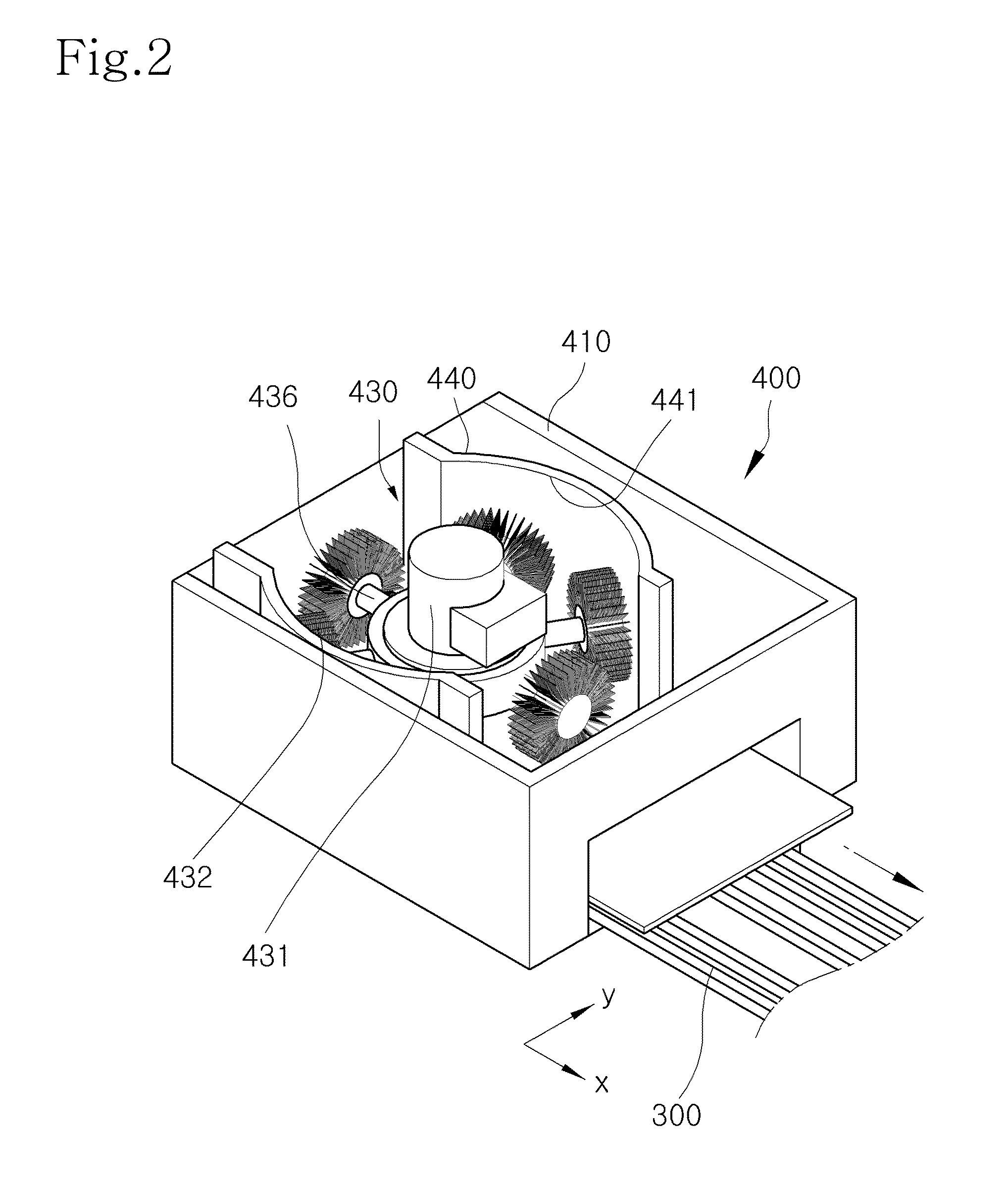
[0029]FIG. 1 is a perspective view showing a deburring apparatus according to one embodiment of the present invention, FIG. 2 is a perspective view showing a part of the internal structure of a deburring module in the deburring apparatus according to one embodiment of the present invention, FIGS. 3 and 4 are views showing the deburring procedure using the deburring apparatus according to the embodiment of t...


PUM

PropertyMeasurementUnit
transparentaaaaaaaaaa
semi-transparentaaaaaaaaaa
rotation radiusaaaaaaaaaa

Abstract

Disclosed is a deburring apparatus. The deburring apparatus includes a transfer module installed on a base to form a transfer path of transferring a workpiece to be deburred, a deburring module provided on the transfer path of the workpiece installed on the base to deburr the workpiece, and a blocking cover installed on the base to reciprocate thereon to selectively prevent the transfer module and the workpiece on the transfer module from being exposed to an outside, and to prevent dust and noise, which are produced when a deburring work is performed for the workpiece by using the deburring module, from being delivered to the outside. The burrs, which are produced when a metallic produce or a non-metallic produce having a 3-D shape is molded or cut, are easily and rapidly removed.

Description

BACKGROUND OF THE INVENTION[0001]1. Field of the Invention[0002]The present invention relates to a deburring apparatus. In more particular, the present invention relates to a deburring apparatus capable of reducing the contamination of a working place caused by noise and foreign matters produced in a deburring work while automatically removing burrs produced when a metallic product or a non-metallic product is molded or cut.[0003]2. Description of the Related Art[0004]in general, in order to remove burrs of a workpiece, as disclosed in Korean Patent Unexamined Publication No. 10-2009-0132935, a worker has manually performed a deburring work by using a drilling tool or a hand tool such as sand paper. In addition, in a case that an automation arrangement has a very complex internal shape, the mechanical design of the automation arrangement to remove burrs is very difficult. Accordingly, the burrs have been manually removed.[0005]However, a scheme to manually remove the burrs may incre...

Claims


Application Information

Patent Timeline
Patent Type & Authority Applications(United States)
IPC IPC(8): B24B27/00
CPCB24B27/033B24B9/00B24B55/04B29C37/02B24B41/06
Inventor CHEON, KYEONG HO
Owner KOREA AEROSPACE INDUSTRIES
Learn More