Control apparatus for motor-generator

a control apparatus and motor technology, applied in the direction of dynamo-electric machines, synchronous motor starters, electric variable regulation, etc., can solve the problems of lowering system efficiency, reducing and the driving method is not suitable for use, so as to simplify the magnetic pole position sensor, reduce the cost of operation, and improve the efficiency of the system

Active Publication Date: 2013-04-25
DENSO CORP
View PDF3 Cites 3 Cited by
  • Summary
  • Abstract
  • Description
  • Claims
  • Application Information

AI Technical Summary

Benefits of technology

[0006]An embodiment provides a control apparatus for a motor-generator. In the apparatus, a simplified magnetic pole position sensor is provided. Even if the number of times of switching is decreased, an excellent rotating speed characteristic can be obtained. Hence, cooling and protection against noise can also be simplified.

Problems solved by technology

Hence, an expensive magnetic pole position sensor is required.
In addition, since all elements are required to be subject to switching, switching losses increase, thereby lowering the system efficiency, a large cooling unit is required for the inverter, and protection against switching noise is required.
Accordingly, although the driving method can be used for an expensive apparatus, the driving method is not suited to be used for, in particular, electric components for a light automobile and a motorcycle from a cost viewpoint.

Method used


Image

  • Control apparatus for motor-generator
  • Control apparatus for motor-generator
  • Control apparatus for motor-generator

Examples


first embodiment

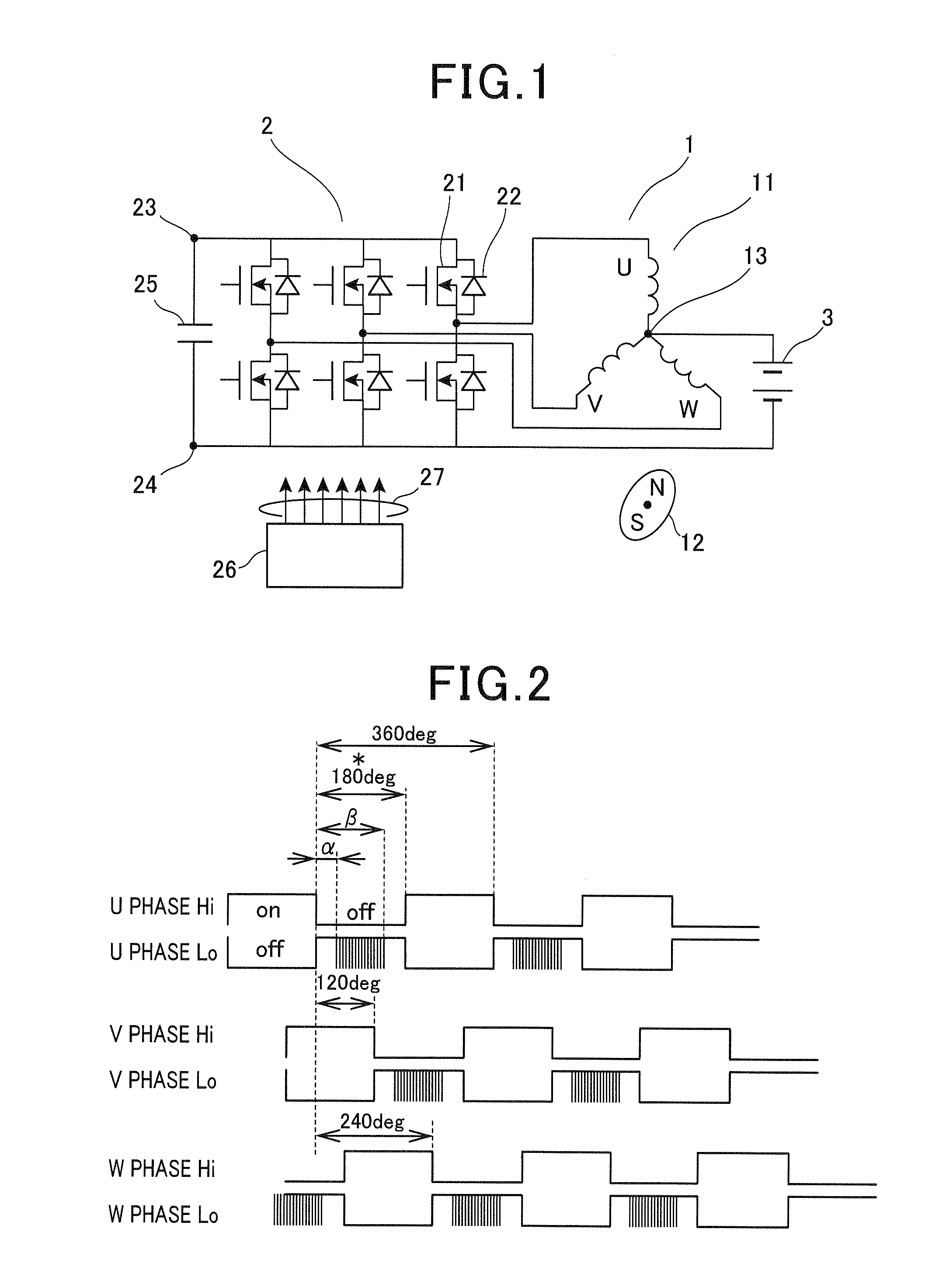
[0021]FIG. 1 shows a configuration of the first embodiment. A motor-generator 1 includes a stator 11 and a rotor 12. The rotor 12 may be a permanent magnet type, a wound-field type, or a cage-type inductor. The rotor 12 may have a magnetic salient-pole type reluctance structure which has no coil and no magnet.

[0022]The stator 11 is provided with three-phase coils which are connected so as to form a star shape. Ends of the three-phase coils are connected at a neutral point 13. The other ends of the three-phase coils are connected to an inverter 2.

[0023]In the inverter 2, a switch element 21 and a free wheeling element 22 form one arm. The same two arm formations are connected in series. Three of the serial connections are arranged in parallel.

[0024]If the switch element 21 and the free wheeling element 22 are configured by a MOSFET (metal-oxide semiconductor field-effect transistor) and a parasitic diode parasitizing to the MOSFET, mass-produced general-purpose devices can be used. H...

second embodiment

[0037]In the second embodiment, the positive electrode of the DC power supply 3 is connected to the DC positive electrode terminal 23 of the inverter 2. The negative electrode of the DC power supply 3 is connected to the neutral point 13 of the star-shaped connection.

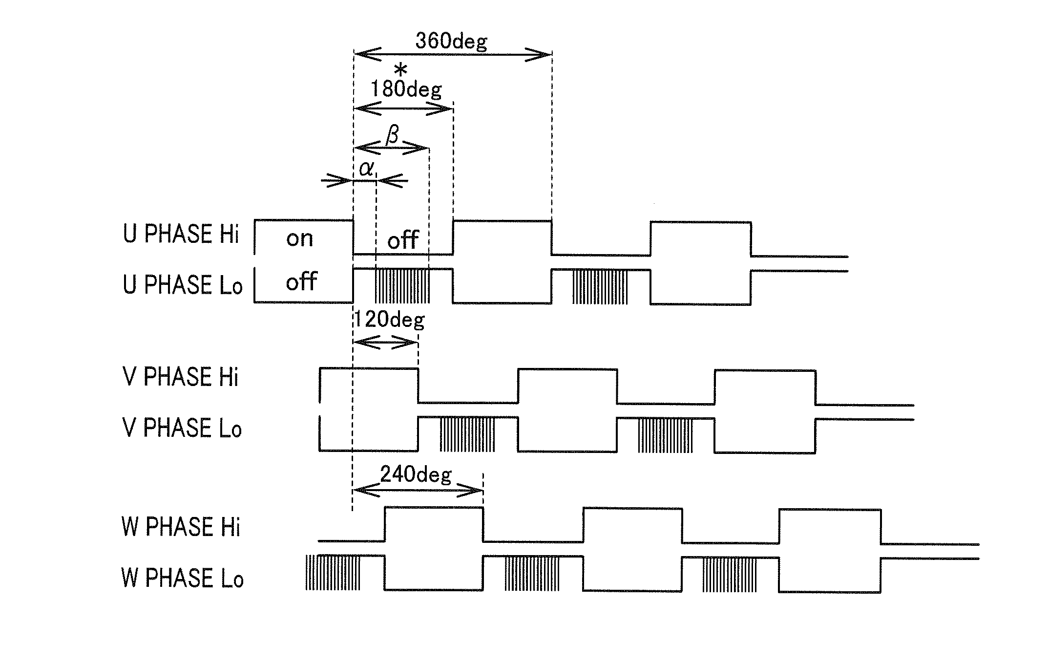
[0038]As shown in FIG. 5, according to the pattern of control, the high-side switch is subject to the PWM control during the period of time during which the low-side switch is in an off-state. Designating the off time point of the low-side switch as a starting point, a and p are defined so as to meet “β-α≧120 degrees”, “α>0 degrees”, and “β180 degrees”.

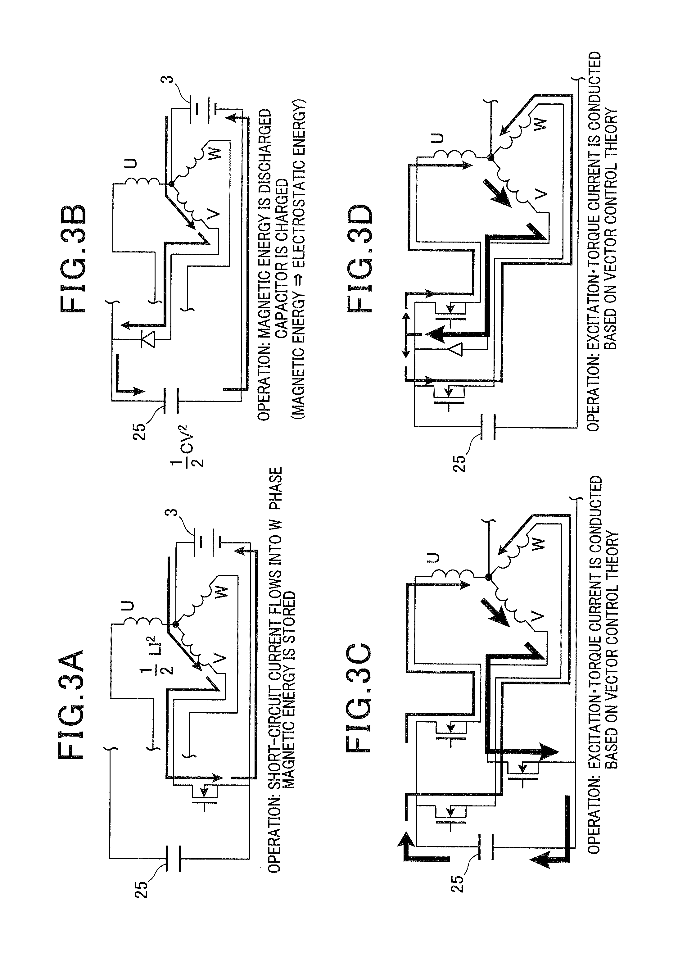
[0039]The operation of the second embodiment is similar to the operation shown in FIGS. 3A to 3D, in which the capacitor 25 is charged via a low-side free wheeling diode.

[0040]As shown in FIG. 10, the control of the above embodiment can increase the driving rotating speed to about twice that of the conventional control which does not increase voltage, even though a dedica...


PUM


Abstract

A control apparatus for a motor-generator includes a stator including multi-phase coils, a rotor, a multi-phase inverter one arm of which includes a switch element and a free-wheeling element, and a power supply connected between a neutral point of the coils and a negative electrode of the inverter. When the switch elements are driven by rectangular wave, the low-side switch element connected to the high-side switch element is subject to PWM switching control while the high-side switch element is off. When a time point, at which the high-side switch element is turned off, is defined as a base point, if α is defined as a time when switching of the low-side switch element starts, and β is defined as a time when the switching ends, β-α is 120 degrees in electrical degree or more, α is more than 0 degrees, and β is less than 180 degrees.

Description

CROSS-REFERENCE TO RELATED APPLICATION[0001]This application is based on and claims the benefit of priority from earlier Japanese Patent Application No. 2011-234304 filed Oct. 25, 2011, the description of which is incorporated herein by reference.BACKGROUND[0002]1. Technical Field[0003]The present invention relates to a control apparatus for a motor-generator, the apparatus being used by changing the operation mode thereof between an electric power generation mode as a generator and a mechanical power generation mode as a motor.[0004]2. Related Art[0005]As a simple speed-increasing method for a brushless motor, a driving method using a circuit disclosed in, for example, JP-A-2008-306914 is known. This example requires a sinusoidal PWM controlled inverter to obtain stable rotational speed extensively. Hence, an expensive magnetic pole position sensor is required. In addition, since all elements are required to be subject to switching, switching losses increase, thereby lowering the s...

Claims


Application Information

Patent Timeline
Patent Type & Authority Applications(United States)
IPC IPC(8): H02K23/52H02P6/14H02P6/08H02M3/155H02M7/48H02P6/06
CPCH02P27/08H02P6/085H02P2209/01H02P2207/05H02P9/302
Inventor TANIGUCHI, MAKOTONAGATA, KOUICHIOSADA, MASAHIKO
Owner DENSO CORP
Why Eureka
Try Eureka