Fluorescence measurement

a fluorescence measurement and sample technology, applied in the direction of instrumentation, material testing goods, component separation, etc., can solve the problems of low fluorescence intensity, short fluorescence lifetime of interest, and considerable practical difficulties, so as to achieve less noise sensitivity, less noise, and simple design

Inactive Publication Date: 2013-04-04
LIGHTSHIP MEDICAL
View PDF2 Cites 8 Cited by
  • Summary
  • Abstract
  • Description
  • Claims
  • Application Information

AI Technical Summary

Benefits of technology

[0024]According to a preferred embodiment, the light detector is a single photon avalanche diode. The intensity of light emitted by the light source is modulated at a first frequency, and the bias voltage applied to the single photon avalanche diode is modulated at a second frequency, different from the first frequency. The bias voltage is above the breakdown voltage of the single photon avalanche diode. This selection of bias voltage means that the single photon sensitivity of the detector is maintained, but also has the advantage that a heterodyne measurement approach can be used. In other words, the resulting measurement signal of interest from the single photon avalanche diode is at a frequency corresponding to the difference between the first and second frequencies. The first and second frequencies may be of the order of 1 MHz or much higher, but may be selected such that their difference is, for example, of the order of 10 s of kHz. Therefore, the operational bandwidth of the measurement electronics can be much lower than the first and second modulation frequencies, allowing a simpler design and with less sensitivity to noise.
[0025]A further advantageous aspect is to introduce a series of additional phase angles (or time delays equivalent to phase shifts) in the modulation signal for the light source. A series of measurements can then be obtained relating the modulation depth of the measurement signal to the introduced phase angle. Analysing these results can improve the overall precision of the fluorescence lifetime measurement.

Problems solved by technology

However, there are considerable practical difficulties, such as the low intensity of the fluorescence light, both in absolute terms and relative to the intensity of the excitation light.
Furthermore, the fluorescence lifetimes of interest, for example in glucose sensing applications, may be extremely short, such as of the order of 10 ns.
This either means that the cost of the pulsed laser is high to achieve the high output stability; alternatively there is a compromise in signal-to-noise and therefore lower precision in the measurement.
Furthermore, the peak power of the laser pulses can be very high resulting in photo-bleaching of the sample under investigation and therefore inaccuracy in the measured intensity of the fluorescence light.
Thus conventional systems for fluorescence measurements are large, cumbersome, have high power requirements, and generally require specialist operators to set up and perform the measurements and obtain useful results.
There are therefore problems in making compact, inexpensive, low-power devices that are simple to use, for example for use in homes or clinics for applications such as medical monitoring, for example of glucose levels in diabetic patients.

Method used


Image

  • Fluorescence measurement
  • Fluorescence measurement

Examples


Embodiment Construction

[0029]The present invention provides a sensor and measurement method for fluorescence measurements. A preferred embodiment relates to the measurement of glucose concentration, as will be described in more detail below. Firstly, the general arrangement and operation of the fluorescence sensor will be explained.

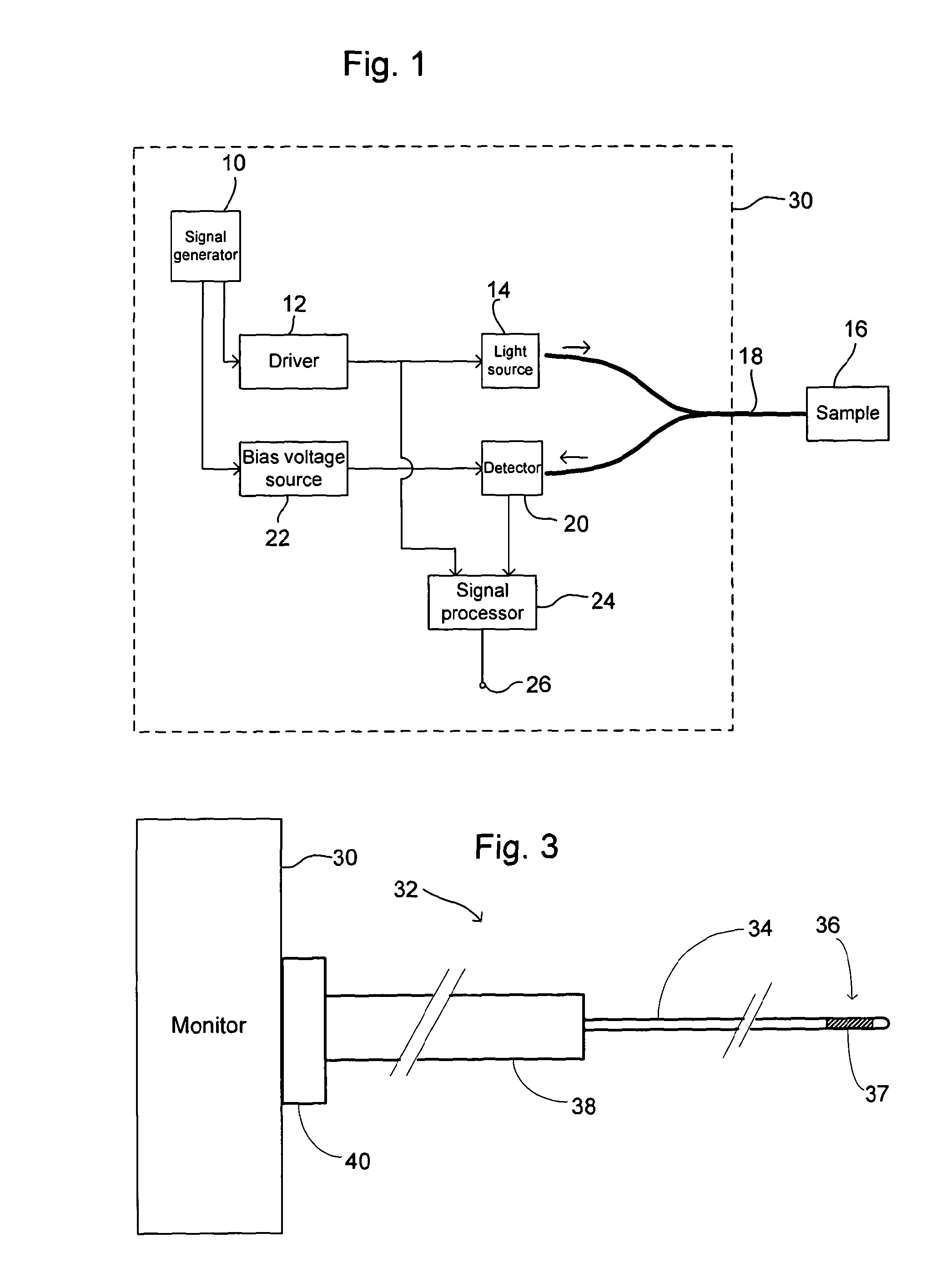
[0030]FIG. 1 shows schematically an embodiment of a fluorescence sensor according to the invention. A signal generator 10 produces a high frequency periodic signal at a first frequency that is passed to a driver 12. The driver 12 may condition the first signal and then uses it to drive modulation of a light source 14. The light source 14 generates the excitation light to be used for stimulation of the fluorescence system being investigated. The light source 14 can be, for example, an LED or laser diode. Preferably the light source 14 is temperature stabilized. The choice of output wavelength of the light source is made to suit the sample under investigation to stimulate a trans...


PUM

PropertyMeasurementUnit
fluorescence lifetimeaaaaaaaaaa
fluorescence lifetimesaaaaaaaaaa

Abstract

A sensor for fluorescence measurement comprising: a light source arranged for emitting light to a sample region, wherein the light source intensity is modulatable; an indicator system located at the sample region, said indicator system comprising: a receptor for an analyte; and a fluorophore associated with said receptor, wherein the fluorophore has a fluorescence lifetime that changes in response to the presence of analyte at the receptor; a single photon avalanche diode arranged to receive fluorescence light emitted from said sample region in response to the light incident on the sample region from the light source, and to generate an output signal; a driver arranged to modulate the light source intensity at a first frequency; a bias voltage source arranged to apply a bias voltage to the single photon avalanche diode, wherein the bias voltage is modulated at a second frequency, different from the first frequency, and wherein the bias voltage is above the breakdown voltage of the single photon avalanche diode; and a signal processor arranged to determine information related to a fluorescence lifetime of the fluorophore based on at least the output signal of the single photon avalanche diode.

Description

FIELD OF THE INVENTION[0001]The present invention relates to a sensor and method for measuring fluorescence of a sample, for example for measuring fluorescence lifetime or for measuring a property of a sample that is related to fluorescence lifetime.BACKGROUND TO THE INVENTION[0002]Fluorescence measurement, particularly measurement of fluorescence lifetimes, is of considerable practical importance in photo-chemistry and photo-physical research. More recently, there has been interest in utilizing fluorescence lifetime measurements for sensor applications. However, there are considerable practical difficulties, such as the low intensity of the fluorescence light, both in absolute terms and relative to the intensity of the excitation light. Furthermore, the fluorescence lifetimes of interest, for example in glucose sensing applications, may be extremely short, such as of the order of 10 ns.[0003]There are two principal methodologies for fluorescence lifetime measurement: time-domain an...

Claims


Application Information

Patent Timeline
Patent Type & Authority Applications(United States)
IPC IPC(8): G01N21/64
CPCG01N21/6408G01N21/7703G01N33/66G01N21/6486G01N2021/772G01N2021/7786G01N2021/6484
Inventor CRANE, BARRY COLINGILCHRIST, JOHNCAIRNS, NEIL
Owner LIGHTSHIP MEDICAL
Why Eureka
Try Eureka