
Method For Controlling A Loading Process Of A Transport Vehicle With Milled Material, Device For Implementing Such A Method And A Milling Device

a technology of transport vehicles and milling machines, which is applied in the direction of loading/unloading, roads, constructions, etc., can solve the problems of poor visibility of the preceding transport trucks, placing stricter requirements on and the milling machine operators cannot see the loading trough completely

Active Publication Date: 2013-03-28
BOMAG
View PDF4 Cites 76 Cited by
  • Summary
  • Abstract
  • Description
  • Claims
  • Application Information

AI Technical Summary

Benefits of technology

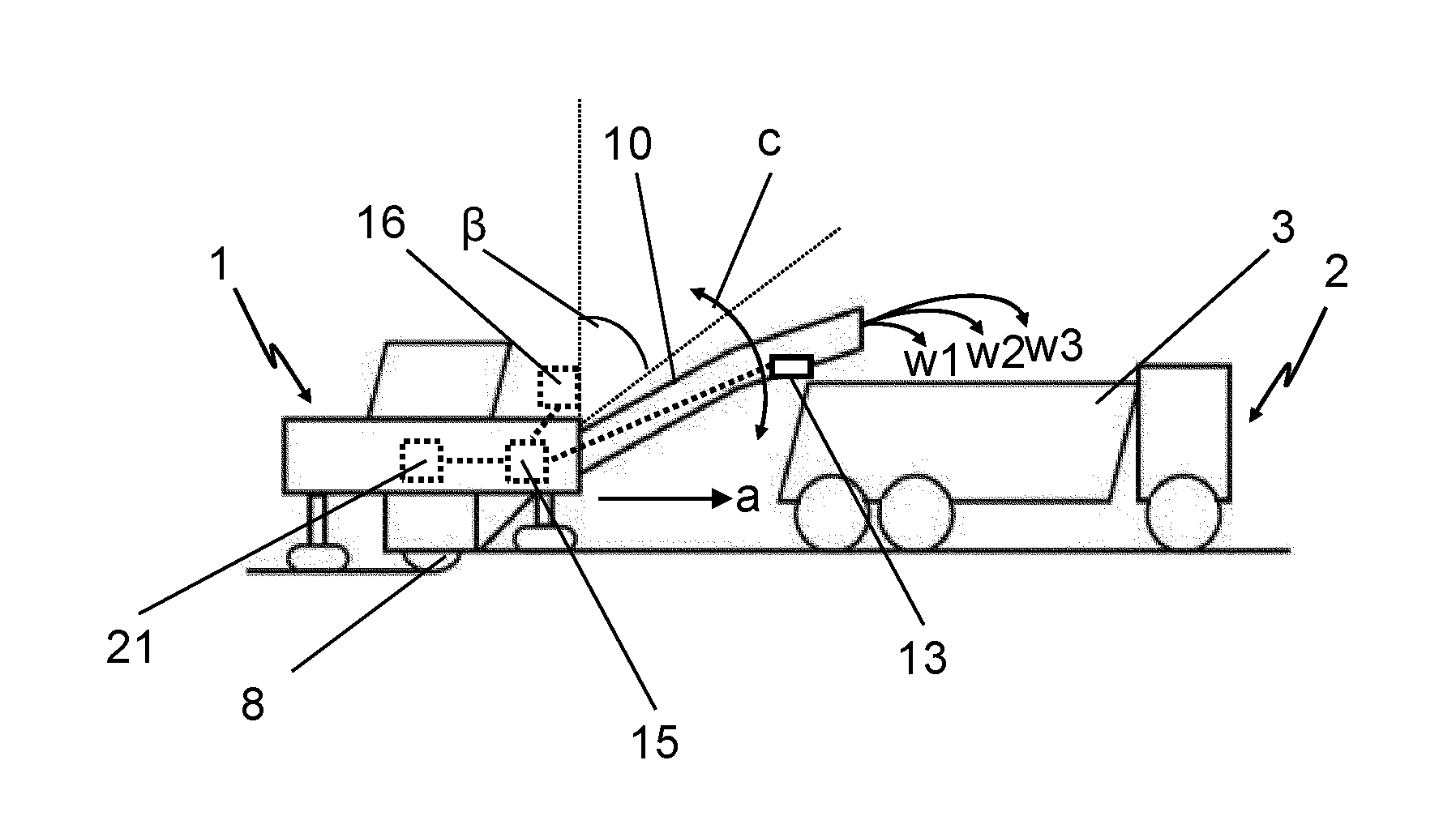
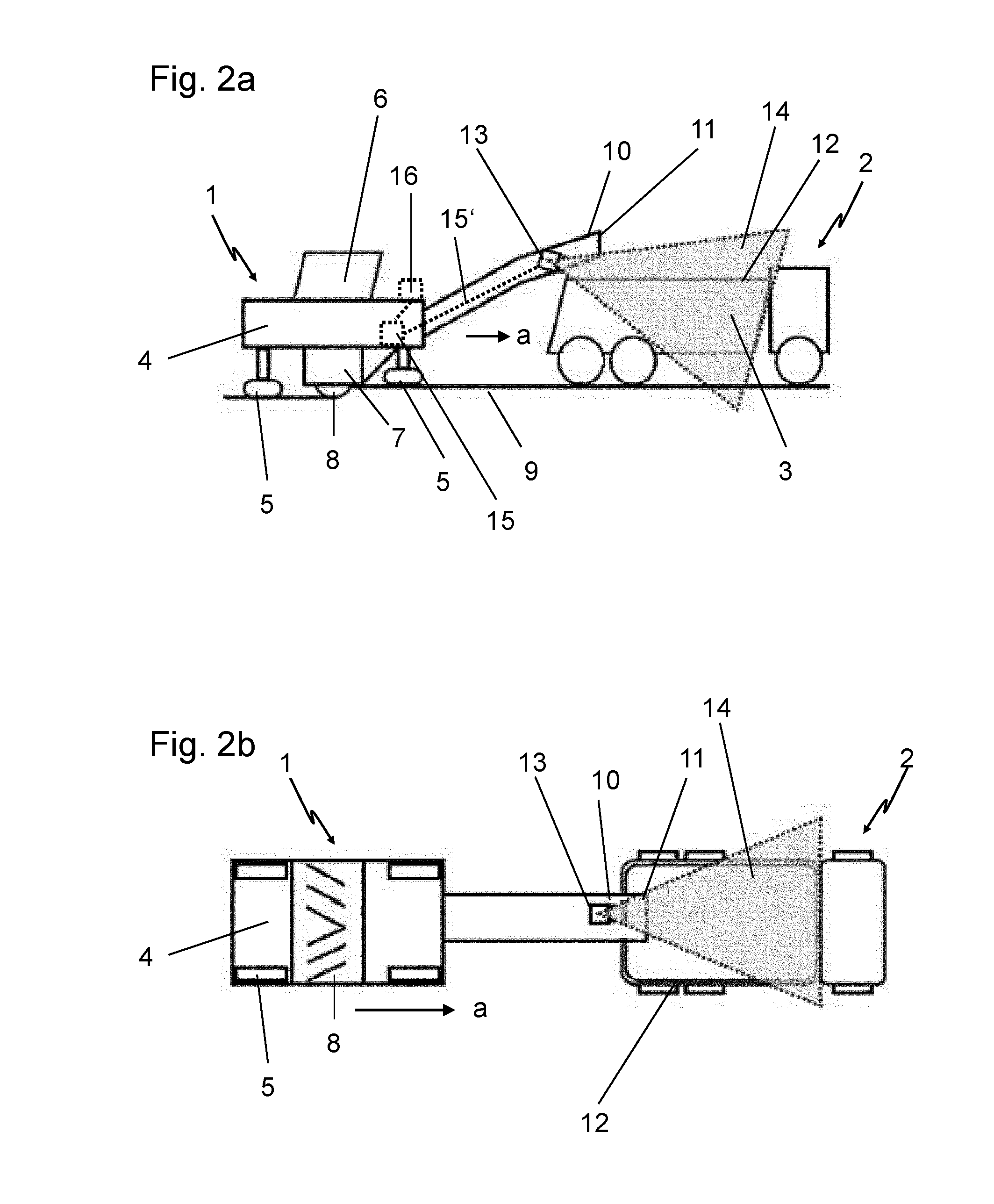
The present invention provides a way to relieve the machine operator of a milling device during the process of loading a transport vehicle. The invention uses a sensor device to detect the position of the transport container in relation to the milling device, and the sensor device automatically monitors the position of the container during the loading process. This eliminates the need for the operator to constantly watch the position of the container, allowing them to concentrate on the actual milling work. The invention also includes a method for controlling the loading process based on the position of the container, and a signal is outputted to the operator when the container is ready for loading or when it is removed. This results in a high accuracy of central loading of the container, ensuring the milled material is distributed to the edge regions by gravity and flow behavior. The sensor device can detect the position of the container using reflectors, transponder elements, or a camera device with at least two mutually spaced imaging elements.

Problems solved by technology

However, especially this loading type normally places stricter requirements on the milling machine operator.
For example, in particular the visibility of the preceding transport trucks is poor and the milling machine operator cannot see the loading trough completely, for instance.
This is especially true when the visibility is also impaired by the local conditions, as is often the case in road construction, for example, due to road curves, narrow roads, traffic flow in the surroundings, ground obstacles, such as manhole covers, etc.
On the one hand, the milled material, which is often milled pavement, has a relatively high density, which can quickly lead to overloading.
On the other hand, the transport trucks commonly used here move at speeds of up to 100 km / h, so that the overloaded vehicles may pose a particularly high safety risk.
This leads to considerable stress to the machine operator.

Method used


Image

  • Method For Controlling A Loading Process Of A Transport Vehicle With Milled Material, Device For Implementing Such A Method And A Milling Device
  • Method For Controlling A Loading Process Of A Transport Vehicle With Milled Material, Device For Implementing Such A Method And A Milling Device
  • Method For Controlling A Loading Process Of A Transport Vehicle With Milled Material, Device For Implementing Such A Method And A Milling Device

Examples


Embodiment Construction

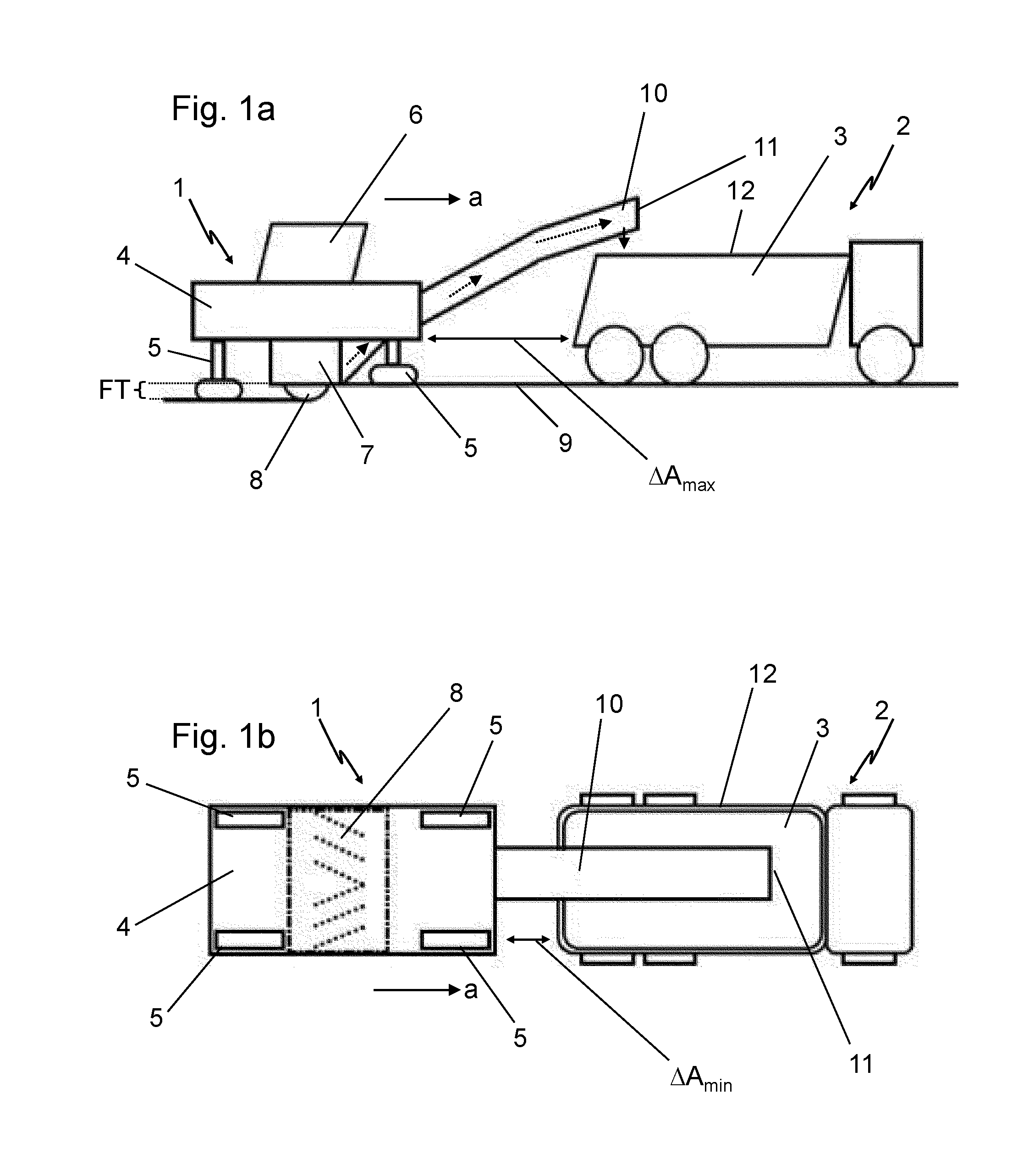
[0037]The FIGS. 1a and 1b illustrate a typical or exemplary work situation of a milling device 1 in side view (FIG. 1a) and in plan view (FIG. 1b). The milling device 1 mills off the soil material in milling operation to the respectively set milling depth FT and transfers this milled material (milled off soil material) into the transport container 3 of a transport vehicle 2 (actually a semitrailer). The milling device 1 comprises for this purpose a machine frame 4, a chassis 5 (comprising a total of four individual lifting columns with caterpillar gondolas), an operator workstation 6 and a milling rotor 8 mounted in a milling roller case 7, extending transversely to the working direction a of the milling device 1 and moving over the soil 9 to be milled off. The milled material is transported via a conveyor designed as a conveyor belt 10 from the milling device 1 to the transport vehicle 2. In the present embodiment, the conveyor belt 10 runs to the front or in the working direction ...


PUM


Abstract

The invention relates to a method for controlling a loading process of a transport vehicle by a milling device in milling operation, a device for implementing this method and a road milling machine or a device for the removal of soil material with such a device. An essential aspect of the invention is a sensor device by means of which the position and partially also the fill level of the transport container of the transport vehicle can be determined.

Description

CROSS-REFERENCE TO RELATED APPLICATIONS[0001]The present application claims priority under 35 U.S.C. §119 of German Patent Application No. 10 2011 114 183.2, filed Sep. 22, 2011, the disclosure of which is hereby incorporated herein by reference in its entirety.FIELD OF THE INVENTION[0002]The present invention relates to a method for controlling a loading process of a transport vehicle with milled material, a device for implementing such a method and a milling device, in particular a road milling machine, with such a device.BACKGROUND OF THE INVENTION[0003]From the prior art, milling devices are known which comprise a machine-frame-supported milling rotor that is arranged transverse to the working direction. In milling operation, such milling devices traverse overground, with the milling rotor submerging in the ground and milling off the soil material with the help of the milling tools arranged on the rotating milling rotor. In milling operation, the milling device thus moves in the...

Claims


Application Information

Patent Timeline
IPC IPC(8): E01C23/088B65G67/04
CPCE01C23/088E01C19/004
Inventor VON DER LIPPE, JORNZAHR, THOMASLANG, MARKUSSCHOMAKER, RAFAELBALDESSARI, FILIPPELAUX, ROBERT
Owner BOMAG
Learn More