
Worm wheel gear for BLDC motor

a worm wheel and motor technology, applied in the direction of gearing elements, belts/chains/gearings, hoisting equipments, etc., can solve the problems of increased noise, user displeased with small operational noise, and difficulty in increasing transmission efficiency, so as to increase the contact area, reduce noise, and increase the efficiency of transmitting power

Inactive Publication Date: 2013-03-28
HYUNDAI MOTOR CO LTD
View PDF12 Cites 1 Cited by
  • Summary
  • Abstract
  • Description
  • Claims
  • Application Information

AI Technical Summary

Benefits of technology

The present invention is a worm wheel gear for a BLDC motor that improves efficiency and reduces noise during operation. By making the contact area between the shift gear and the gear more effective, the gear can transmit power more efficiently and with less noise. This is achieved by making one side of the thread groove open and the other side closed, which increases the contact area with the shift gear.

Problems solved by technology

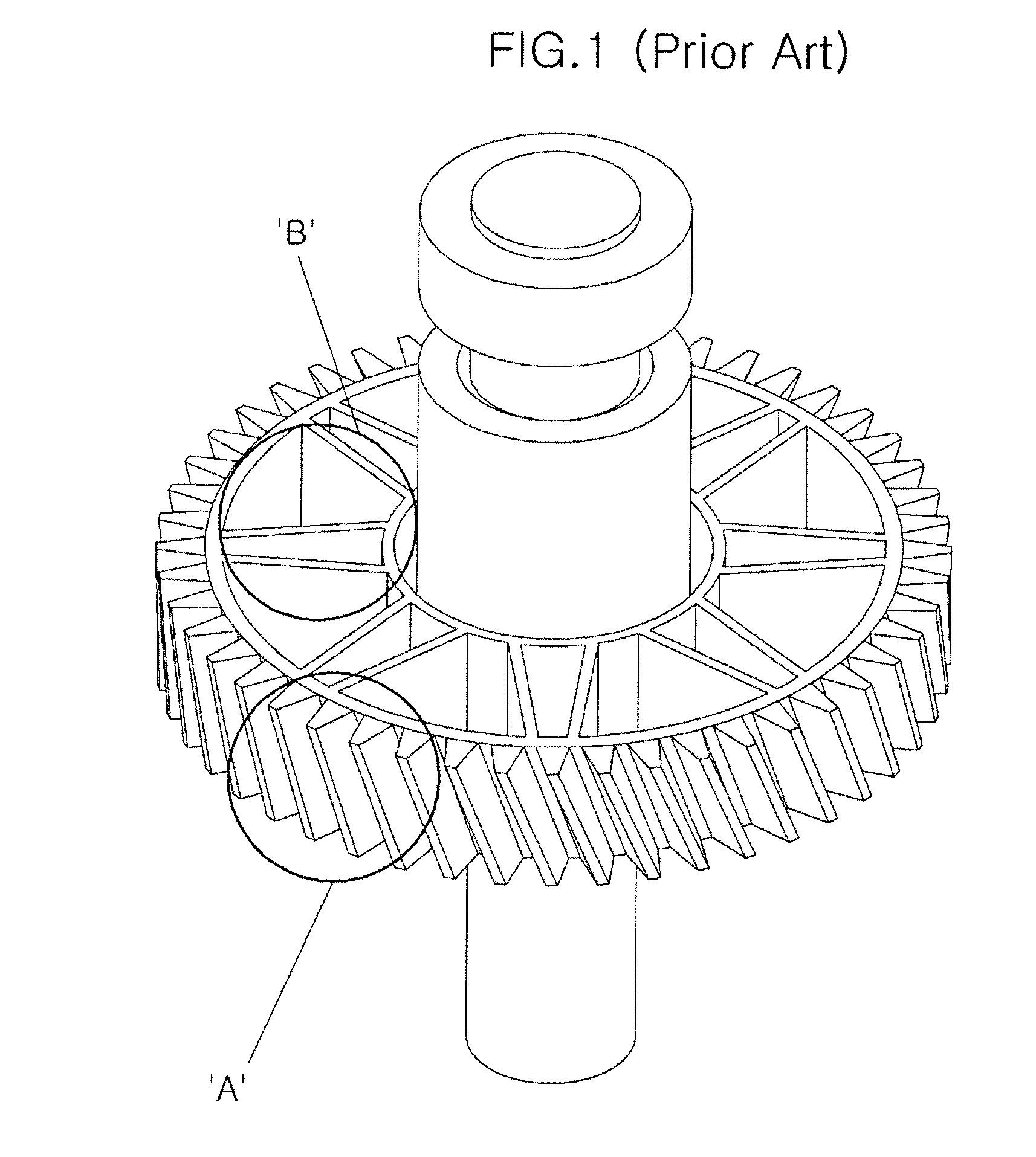
However, in the worm wheel gear for a BLDC motor of the related art, matching is implemented through the ends of the threads to prevent wear or breaking due to an excessive engaging force with the shift gear by the shape indicated by ‘A’, such that it is difficult to increase transmission efficiency by increasing the maximum contact area with the shift gear.
Further, the worm wheel gear for a BLDC motor of the related art has a problem in that noise increases, because stress generated by excessive engagement in matching with the shift gear is easily transmitted to the entire worm wheel gear, including the driving shaft, due to the structure indicated by ‘B’.
In particular, users may be displeased with a small operational noise in a worm wheel gear for a BLDC motor that is applied to a device for driving a sunroof of a vehicle which is disposed close to the users' ears.

Method used


Image

  • Worm wheel gear for BLDC motor
  • Worm wheel gear for BLDC motor
  • Worm wheel gear for BLDC motor

Examples


Embodiment Construction

[0030]Reference will now be made in detail to various embodiments of the present invention(s), examples of which are illustrated in the accompanying drawings and described below. While the invention(s) will be described in conjunction with exemplary embodiments, it will be understood that present description is not intended to limit the invention(s) to those exemplary embodiments. On the contrary, the invention(s) is / are intended to cover not only the exemplary embodiments, but also various alternatives, modifications, equivalents and other embodiments, which may be included within the spirit and scope of the invention as defined by the appended claims.

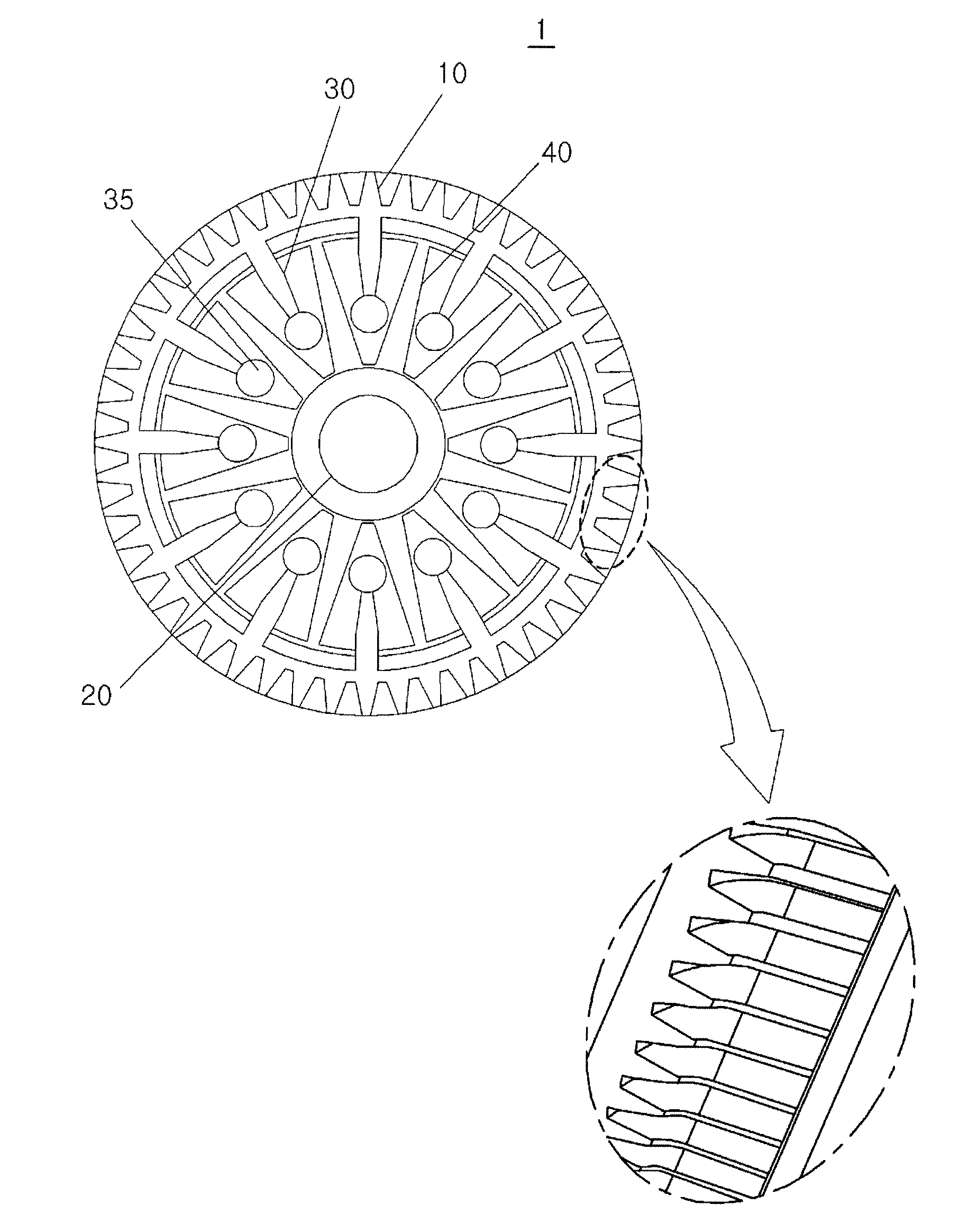
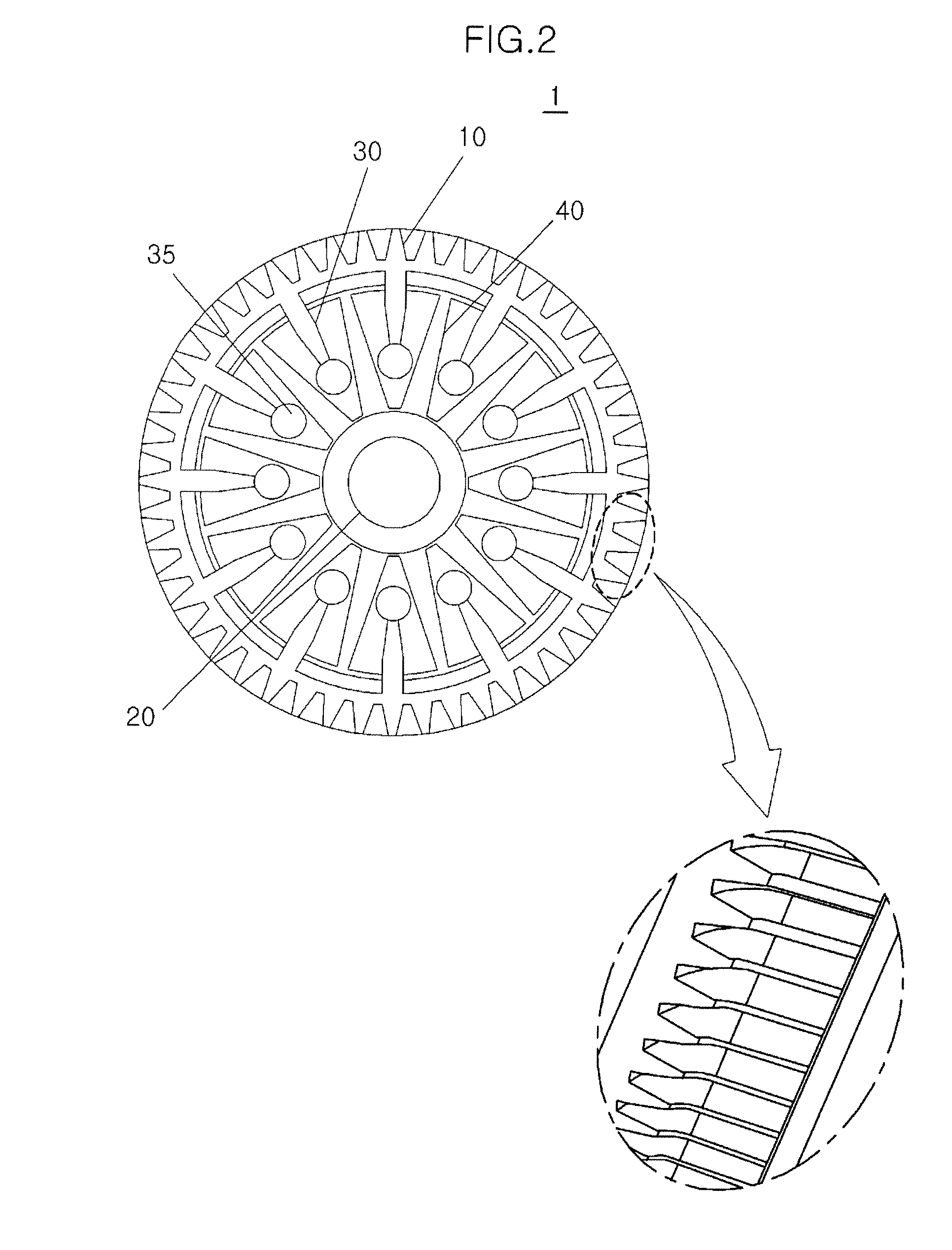
[0031]Referring to FIG. 2, a worm wheel gear 1 for a BLDC motor according to various embodiments includes a worm wheel-threaded portion 10, a work wheel central shaft 20, internal support members 40, and protrusions 30, in order to transmit the operation of a shift gear of an armature unit of the BLDC motor.

[0032]Worm wheel-threaded p...


PUM


Abstract

A worm wheel gear for a BLDC motor transmits the operation of a shift gear of an armature unit in a BLDC motor. The worm wheel gear may include a worm wheel-threaded portion formed on the outer circumferential surface with one side of a thread groove recessed and open and the other side of the thread groove closed, a worm wheel central shaft formed at the center portion, and internal support members protruding from the worm wheel central shaft and connected to the inner circumferential surface of the worm wheel-threaded portion to support the worm wheel-threaded portion. Therefore, it is possible to improve efficiency of transmitting operation and reduce operational noise by increasing the contact surface between the worm wheel-threaded portion and the shift gear.

Description

CROSS-REFERENCE TO RELATED APPLICATIONS[0001]The present application claims the priority of Korean Patent Application Number 10-2011-0096303 filed Sep. 23, 2011, the entire contents of which application is incorporated herein for all purposes by this reference.BACKGROUND OF INVENTION[0002]1. Field of Invention[0003]The present invention relates to a worm wheel gear for a BLDC (sunroof) motor, and particularly, to the shape of a worm wheel gear for efficiently transmitting the operation of a shift gear of the armature unit of a BLDC (Brush-Less Direct Current) motor.[0004]2. Description of Related Art[0005]BLDC motors are motors without a brush to minimize an operational noise and reduce a radio noise and used as a driving source of devices requiring a low noise, such as a device for driving the sunroof of vehicles.[0006]FIG. 1 is a perspective view of a worm wheel gear for a BLDC motor of the related art, which shows the shape of a common worm wheel gear. The worm wheel gear for a B...

Claims


Application Information

Patent Timeline
Patent Type & Authority Applications(United States)
IPC IPC(8): F16H55/17
CPCY10T74/19953F16H55/22F16H55/02F16H55/08
Inventor PARK, HOOSANG
Owner HYUNDAI MOTOR CO LTD
Learn More