Driver having dead-time compensation function

a dead-time compensation and driver technology, applied in the field of drivers, can solve the problems of significant voltage drop of the switch of the inverter under low frequency and light load condition, poor performance of the scalar control in terms of speed dynamic response, speed ratio control, etc., and achieve excellent insusceptibility to frequency fluctuation and low cost

Active Publication Date: 2013-03-14
DELTA ELECTRONICS INC
View PDF3 Cites 24 Cited by
  • Summary
  • Abstract
  • Description
  • Claims
  • Application Information

AI Technical Summary

Benefits of technology

[0009]An object of the invention is to provide a driver having dead-time compensation function for compensating the negative effects caused by dead-time by way of the direct feedback of the output current. Thus, the waveform of the output current is approximate to the sinusoidal wave and the frequency of the output current is synchronous with the frequency indicated in the frequency command. In this manner, the manufacturing cost of the inverter is reduced and the driver is applicable to various motors.
[0010]To this end, a broad aspect of the invention is to provide a driver having dead-time compensation function for outputting an output voltage according to a voltage command and a frequency command to drive a load. The inventive driver includes an inverter operating with a pulse-width modulation mode for receiving a DC voltage to output the output voltage and an output current to the load; an output current detector connected to a current loop of the output current for detecting the output current and outputting an output current detecting signal accordingly; and a control unit connected to the inverter and the output current detector for outputting a switching control signal with a dead time to the inverter according to the voltage command and the frequency command, thereby driving the inverter to operate with the pulse-width modulation mode. The control unit is configured to correct a reference command which is varied along with the voltage command and the frequency command according to the output current detecting signal and the dead time, thereby compensating the output voltage, the amplitude and the smoothness of a waveform of the output current.

Problems solved by technology

Although the scalar control has a poor performance in terms of speed dynamic response, speed ratio control, and the precision control, it has been widely employed in non-server applications as the control architecture of the scalar control is simple, easy, and convergent.
Although the voltage / frequency control scheme is easy to implement, the error of the output voltage of the inverter under the low frequency and light load condition will aggravate as the output voltage of the inverter is low and the voltage drop of the switches of the inverter is significant.
Thus, the control performance of the motor under the low frequency and light load condition is poor.
Also, as the power transistors the inverter have non-ideal characteristics such as turn-on delays and turn-off delays, the power transistors will not turn on or off immediately when the input commands are applied thereto.
Nonetheless, the dead time may cause a difference between the actual output voltage and the voltage commands.
More disadvantageously, the dead time would cause the waveform of the output current to be distorted.
By using such dead-time compensation scheme of FIG. 1A, the current waveform will be seriously distorted under a high output voltage condition, and the voltage compensation quantity will be too much as the compensation quantity of the trapezoid compensation curve is inconsistent with the actual compensation quantity.
However, as the dead-time compensation scheme of FIG. 1B requires an additional voltage detector 14, the cost of hardware circuitry is elevated.
However, these conventional dead-time compensation schemes will cause the voltage compensation quantity and the slope of the trapezoid compensation curve to deviate from the ideal value.
Thus, the waveform of the output current is distorted.
In this manner, the rotation speed of the motor will be non-uniform, which means that the rotation speed of the motor will alternate between slow and fast.
The cost of hardware circuitry of the inverter will increase accordingly.

Method used


Image

  • Driver having dead-time compensation function
  • Driver having dead-time compensation function
  • Driver having dead-time compensation function

Examples


Embodiment Construction

[0017]An exemplary embodiment embodying the features and advantages of the invention will be expounded in following paragraphs of descriptions. It is to be realized that the present invention is allowed to have various modification in different respects, all of which are without departing from the scope of the present invention, and the description herein and the drawings are to be taken as illustrative in nature, but not to be taken as a confinement for the invention.

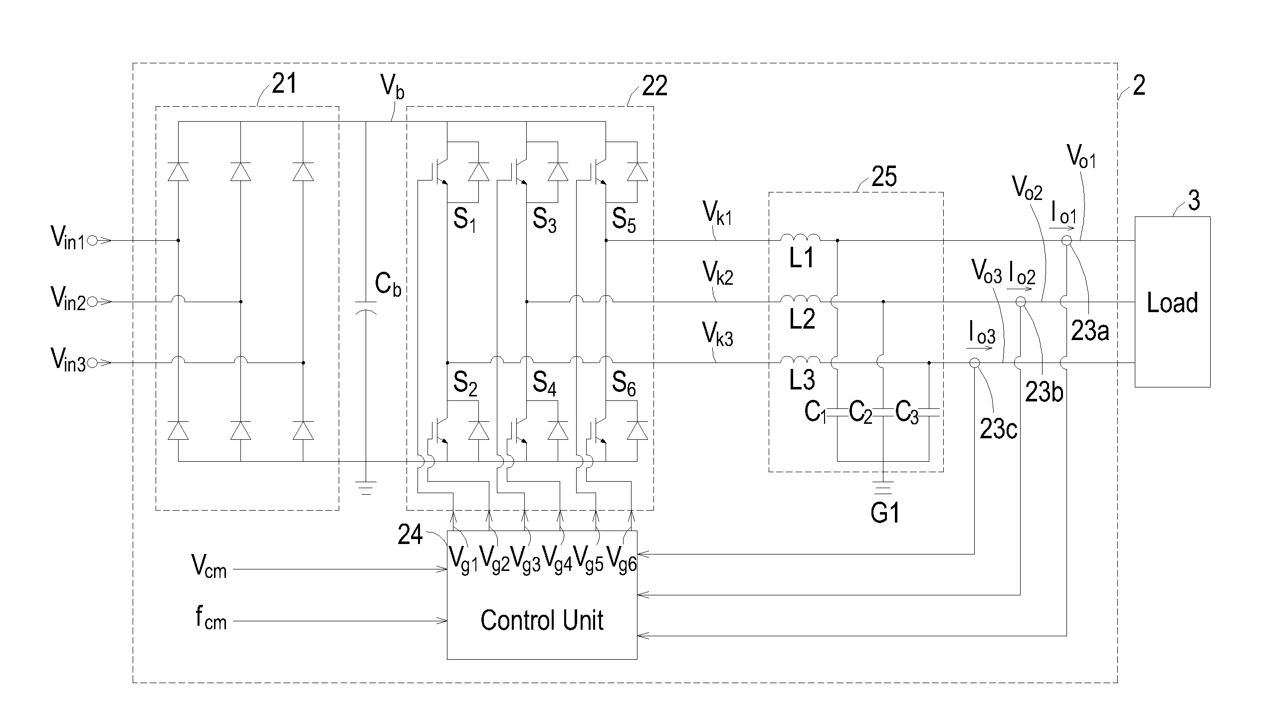
[0018]Referring to FIG. 2A and FIG. 2B, in which FIG. 2A shows the circuitry of the driver having dead-time compensation function according to an exemplary embodiment of the invention, and FIG. 2B shows the block diagram of the control blocks within the control unit according to the exemplary embodiment of the invention. As shown in FIG. 2A, the driver 2 having dead-time compensation function according to the invention is used to receive a single-phase or a three-phase input voltage Vin1-Vin3 from a power supply system...


PUM


Abstract

Proposed is a driver having dead-time compensation function. The driver having dead-time compensation function generates an output voltage according to a voltage command and a frequency command. The driver includes an inverter, an output current detector and a control unit. The inverter receives a DC voltage and operates with a pulse width modulation mode so that the driver outputs the output voltage and an output current. The output current detector detects the current value of the output current to generate a output current detecting signal. The control unit outputs a switching control signal to inverter according to the voltage command and the frequency command. The control unit corrects a reference command according to dead-time and the output current detecting signal related to the output current so that amplitude and waveform smoothness of the output voltage and the output current are compensated.

Description

FIELD OF THE INVENTION[0001]The invention is related to a driver, and more particularly to a driver having a dead-time compensation function.BACKGROUND OF THE INVENTION[0002]The contemporary control technique of using an inverter to drive a motor and control the rotation speed of the motor at the same time is generally classified into scalar control or vector control. Although the scalar control has a poor performance in terms of speed dynamic response, speed ratio control, and the precision control, it has been widely employed in non-server applications as the control architecture of the scalar control is simple, easy, and convergent. The scalar control is also termed as V / f control, or a variable voltage variable frequency control (VVVF). Generally, the scalar control is an open-loop control scheme without the need of the feedback information about the rotation speed of the motor. The basic principle of the scalar control is that the frequency of the power outputted to the motor, ...

Claims


Application Information

Patent Timeline
Patent Type & Authority Applications(United States)
IPC IPC(8): H02P6/14
CPCH02M2001/385H02P27/08H02M1/385
Inventor CHI, CHIEN-YUHUANG, CHIEN-PING
Owner DELTA ELECTRONICS INC
Why Eureka
Try Eureka