
Partial hip prosthesis

a hip joint and prosthesis technology, applied in the field of partial hip joint prosthesis, can solve the problems of limiting the duration of artificial joints, biological sequelae, revision surgery, etc., and achieve the effects of reducing friction and wear, low friction coefficient, and high abrasion resistance against the bon

Inactive Publication Date: 2013-03-07
TEPIC SLOBODAN
View PDF6 Cites 10 Cited by
  • Summary
  • Abstract
  • Description
  • Claims
  • Application Information

AI Technical Summary

Benefits of technology

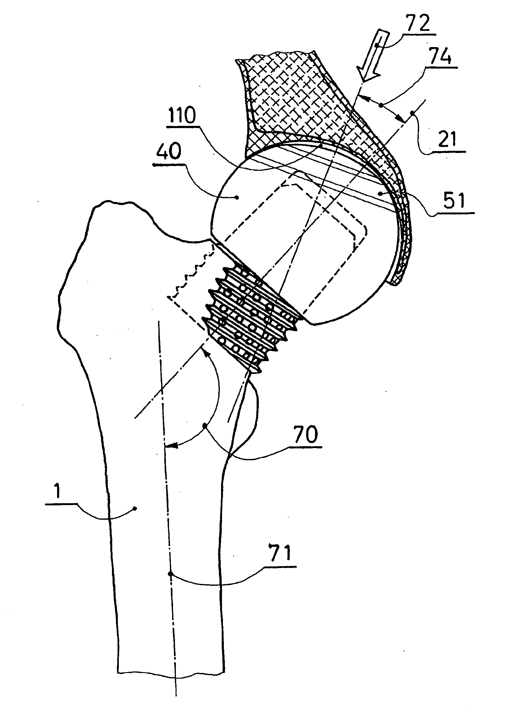
The invention is about improving hip joint replacement by combining optimized geometry and surface treatment of the prosthetic components. The acetabulum is reamed and the femoral head prosthesis or the femoral neck is fixed to the femur. A fluid-filled gap is formed between the two components, which is sealed by an annular area of contact and reduces friction and wear. The surface treatment results in low friction and high abrasion resistance against the bone. The prosthetic head is fixed to the femur using a cylindrical prosthetic neck abutting the reamed femoral neck from outside the medial-inferior cortex, while engaging the lateral-superior area of the femoral neck from within. The prosthetic neck leaves a substantial mass of the cancellous bone of the proximal femur intact, while providing a very stable load transfer to the calcar cortex. The surface of the head is highly polished prior to coating to minimize wear of the bone.

Problems solved by technology

The latter are performed almost exclusively for older patients with femoral neck fractures, mostly due to trauma, and can only be used if the acetabulum is still covered by cartilage.
Both types are generally performing satisfactorily, but both are also leading to a number of complications which can be attributed to sub-optimal performance of either the articulation itself or fixation to the bone.
Wear of the materials used for articulation in the total hip replacement often leads to biological sequelae that may require a revision surgery with new implants.
Wear of Ultra High Molecular Weight Polyethylene (UHMWPE), still the most commonly used articulation material, is considered a major contributing factor to aseptic loosening and thus limiting the duration of artificial joints.
Wear particles produced by articulation of the hard, convex, metallic, or ceramic component against the soft polymer liner accumulate in and around the joint until the concentration of particles becomes so high that, in spite of the polymer's generally excellent biocompatibility when in bulk, they initiate a biological response leading ultimately to bone loss, loosening of the joint components and dysfunction of the joint replacement.
Laboratory testing has shown great variability, mostly due to the different methods of wear production and assessment employed.
Among them is the reduction of strength, particularly in fatigue; reduction of average particle size, making the wear debris biologically more active; and risk of long term degradation in the body.
Several clinical observations suggest actual wear reduction of about factor two, but again, there is much variability in methods used to assess the wear and thus in the reported results.
However, systemic accumulation of ions of potentially harmful metals has been observed, and the risks remain unknown, especially in younger patients, who are most in need of improved joint replacements.
Ceramic-ceramic articulations are technically the best in terms of wear, but various regulatory obstacles and high prices have, until recently, kept their use to a small percentage of the total.
There are also risks, if relatively low, of component breakage due to the extreme brittleness of ceramics and rapid degradation of the articulation caused by minuscule imperfections of, or damage to the surfaces.
Sophisticated technologies and quality controls required in production have also been an impediment to their wider use.
More recently, ceramic-ceramic articulations have seen another major setback in clinical acceptance, when a significant number of them were found to produce a squeaking noise with every step of the patient.
In both cases a mismatch is produced by replacing a single radius of curvature with two, with offset centers, resulting in a line contact.
Only minimal improvement of long term outcomes could be expected from such a procedure.
The disadvantage of this solution is in the high stresses produced at the edge of the recess, which could lead to localized wear, potentially to loss of the seal and hence of hydraulic support.
However, grooves as disclosed may in fact lead to higher local stresses at the edges of the grooves and defeat the purpose.
There has been no published data supporting the concept and no evidence of even limited acceptance of this approach by the orthopaedic device industry.
Functional limitations of partial prosthesis are largely related to a relatively short life of the acetabular cartilage, which, when worn out, leads to a painful joint due to poor frictional properties of the metal-on-bone or ceramic-on-bone articulation.
However, there are problems with the proposed mechanism.
Once cartilage is damaged, movement will shift to the inner articulation, but the large head, with its poor frictional properties, will still occasionally move and wobble within the bony bed.
This leads to surface damage of the relatively soft outer head and accelerates wear at the bone to outer head articulation.
All along, the position of the outer head on the inner one is not ideal, leading to both impingement of the outer head on the neck of the stem and loss of the articulating surface within the acetabulum.

Method used


Image

  • Partial hip prosthesis
  • Partial hip prosthesis
  • Partial hip prosthesis

Examples


Embodiment Construction

[0090]For a simple and clear presentation, a human total hip joint articulation has been chosen for this disclosure, but the same technical arguments and design approaches can be used for a hip prosthesis for animals, specifically for dogs and cats.

[0091]The present invention is an extension of a prior invention by the inventor as set forth in PCT Patent Application No. WO2008 / 058756, published on May 22, 2008, which is incorporated herein, in its entirety, by reference (“the Tepic Application”). The Tepic Application discloses a joint prosthesis, such as a hip prosthesis, in which the convex and concave components have differences in shape to provide a broad contact surface. As set forth in the Tepic Application, the differences in shape between the components further provide improved lubrication of the components and particularly the contact surface. While that structure results in significantly reduced wear, it may still be of a concern, particularly when the concave component is...


PUM

PropertyMeasurementUnit
diameteraaaaaaaaaa
diameteraaaaaaaaaa
diameteraaaaaaaaaa

Abstract

The invention reduces friction and wear in partial hip prosthesis by combining optimized geometry of the articulation and surface treatment of the prosthetic component. The acetabulum is reamed to the bone. One of the articulating surfaces—either that of the reamed acetabulum, or that of the femoral head prosthesis is a-spherical so that a fluid-filled gap is formed at the area of major load transfer. The fluid-filled gap is sealed by an annular area of contact, over which the concave and the convex components are congruent. The preferred surface treatment is by diamond-like coating, which results in very low coefficient of friction and high abrasion resistance against the bone. The prosthetic head is fixed to the femur by either a conventional stem, a perforated shell, or a femoral neck prosthesis screwed onto the femur so that it is partially covered by bone and partially exposed on the medial-inferior aspect, where it abuts the reamed cortex of the calcar region.

Description

BACKGROUND[0001]1. Field of the Invention[0002]The invention relates to partial hip joint prostheses. More particularly, it relates to a hip prosthesis comprising a prosthesis for the head of the femur intended to articulate against the reamed bone of the pelvis, wherein the shape of the articulation is such that only an annular contact is possible. The prosthetic head is coated with a friction—reducing coating such as amorphous diamond-like coating. The head is affixed to the femur by attaching it to either the bone of the femoral head, the femoral neck or the shaft of the femur.[0003]2. Discussion of Related Art[0004]Currently used prostheses of the hip joint are either total hip prostheses, wherein joint articulation occurs between a femoral component and an acetabular component of the prosthesis, or partial hip prostheses, wherein only the femoral side is replaced and articulated against the natural acetabulum. The latter are performed almost exclusively for older patients with ...

Claims


Application Information

Patent Timeline
Patent Type & Authority Applications(United States)
IPC IPC(8): A61F2/36A61B17/16
CPCA61F2/3601A61F2310/0058A61F2/4607A61F2002/30327A61F2002/30332A61F2002/30673A61F2002/30738A61F2002/3085A61F2002/30909A61F2002/30934A61F2002/3623A61F2002/3692A61F2220/0033A61F2250/0039A61F2/3603A61F2002/30593A61B17/1668A61F2002/30354A61F2002/30581A61F2002/365
Inventor TEPIC, SLOBODAN
Owner TEPIC SLOBODAN
Learn More