
Disposable cutting head for clippers

Inactive Publication Date: 2006-03-14
LAUBE KIM
View PDF3 Cites 22 Cited by
  • Summary
  • Abstract
  • Description
  • Claims
  • Application Information

AI Technical Summary

Benefits of technology

[0010]One object of the present invention is an improved cutting head structure for clippers which lowers friction and improves heat dissipation of the combination cutting head and blades to allow for a disposable clipper cutting head assembly. Another object is to reduce warpage of the head and / or blades during use in cutting to minimize hair pulling caused by hair becoming caught between the cutting blades rather than being cleanly cut. A further object is a disposable head and blade design which may be used with existing clip on combs. Another object is adaption of the cutting head for use with spring lock comb elements. A still further object is an upper cutting blade shoe structure for reduced friction wear of a clipper drive lug, which is usually plastic material, to which the upper blade shoe is engaged during clipper reciprocal drive operation. Another object is shielding of the clipper cavity which receives the cutting head to reduce the amount of hair or fur entering therein during a cutting operation. Yet another object is incorporation of protrusions in the base member to accommodate a variety of size of clipper blade socket mounting apparatus.

Problems solved by technology

If desired, the blades alone may be disposed and the head assembly reused; however, the structure is not intended for long wear and use.
U.S. Pat. No. 4,765,060, issued Aug. 23, 1988 discloses a bend in the blade ends which may cause problems of separation as a result of a lack of a continuous concave shape along the longitudinal axis.
Such cut outs can cause loss of lubricants and also serve as a point that may catch and pull hair.

Method used


Image

  • Disposable cutting head for clippers
  • Disposable cutting head for clippers
  • Disposable cutting head for clippers

Examples


Embodiment Construction

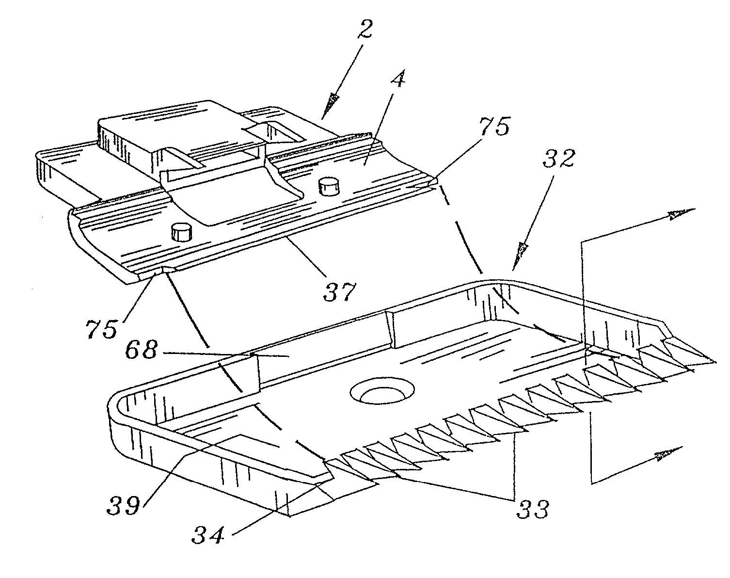
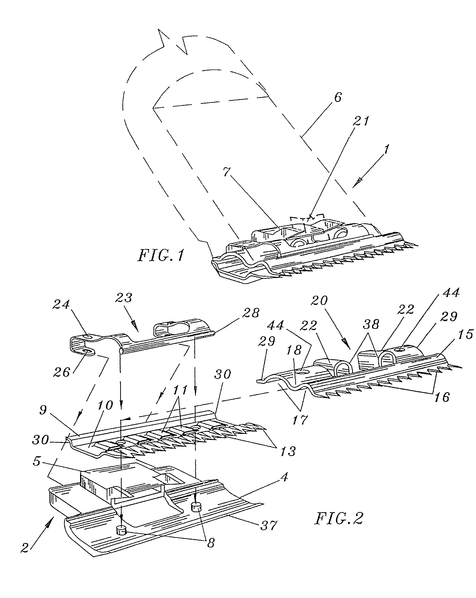
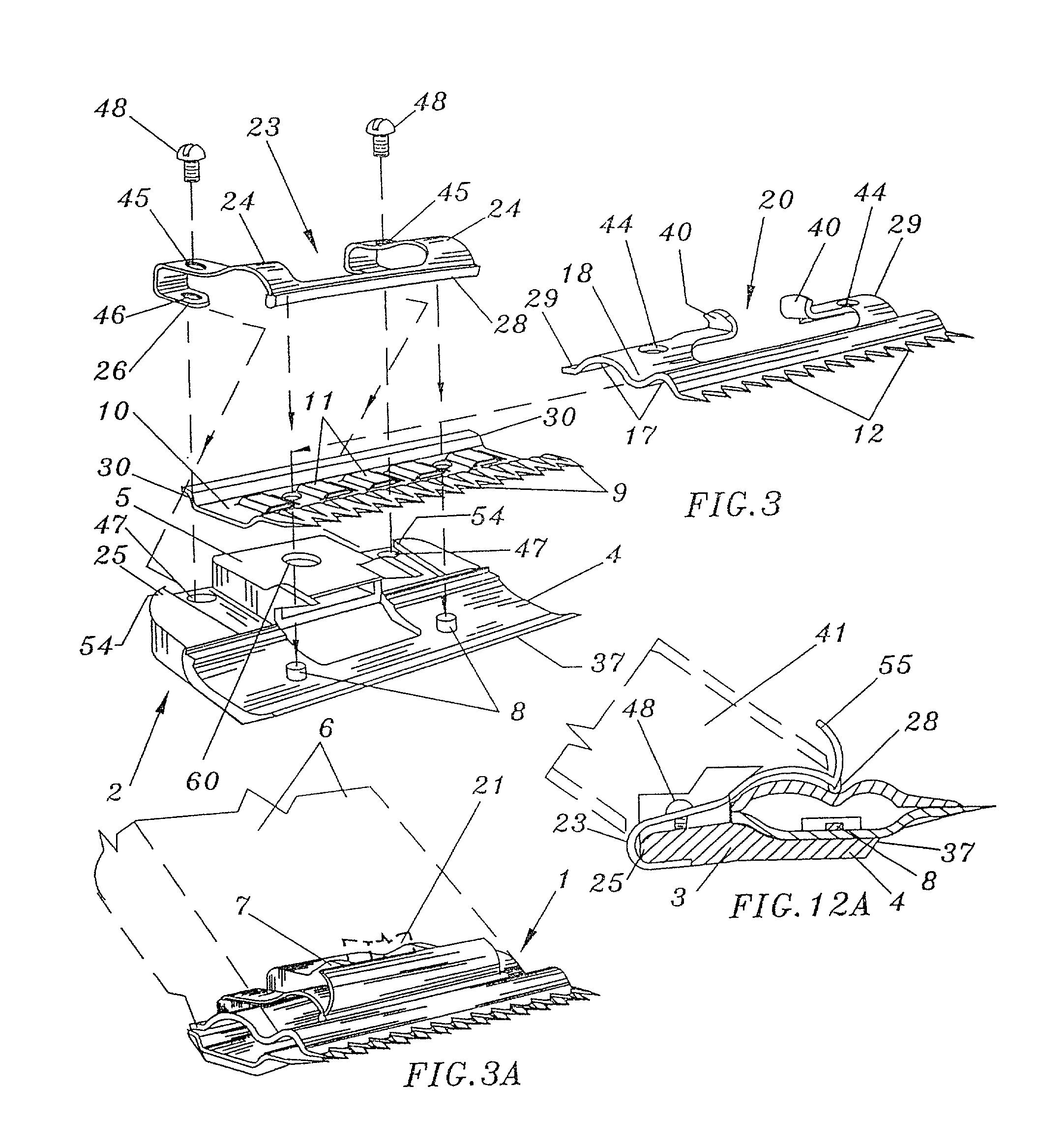
[0046]The disposable cutting head is basically a four element clip together assembly with a base, lower and upper cutting blades, and spring. The base serves as the support for the entire assembly and incorporates the attachment elements for razz retention to a clipper. The spring holds the elements together, forces the cutting blades together and includes the runner under which the upper blade slides. Attachment of a comb element may also be included. Alternate embodiments are described which use screw retention means for the spring and which use a spring lock for retention of comb elements. A plastic comb element for use with the spring lock retention means is incorporated. A deflector plate may be added to the spring structure to inhibit hair entering the clipper cavity.

[0047]Referring to FIGS. 1 through 15, disposable cutting head (1) has base member (2) having a rear mounting portion (3) and lower blade support portion (4). The rear mounting portion (3) has an upstanding centra...


PUM


Abstract

The disposable cutting head is basically a four element clip together assembly with a base, lower and upper cutting blades, and spring. The base serves as the support for the entire assembly and incorporates the attachment elements for retention to a clipper. The spring holds the elements together, forces the cutting blades together and includes the runner under which the upper blade slides. The entire assembly is such that the head assembly with blades is of the disposable type, but uses metal blades. If desired the blades alone may be disposed and the head assembly reused; however, the structure is not intended for long wear and use. The head and blades are constructed such that the common problems encountered with existing removable / disposable heads and blades as for example heat retention in the blades and head and the catching and pulling of hair are minimized. Use with clipper comb elements is also accommodated.

Description

CROSS-REFERENCE TO RELATED APPLICATIONS[0001]This is a divisional application of U.S. patent application Ser. No. 09 / 610,645 filed Jun. 27, 2000, now U.S. Pat. No. 6,393,702 filed Dec. 29, 1998 that is a continuation-in-part of U.S. patent applications Ser. No's. 09 / 457,454 filed Dec. 8, 1999 now abandoned and 09 / 222,049 now abandoned. application Ser. No. 09 / 610,645 is pending.BACKGROUND OF THE INVENTION[0002]1. Field of the Invention.[0003]This invention relates to devices used to clip or cut hair, fur and the like of humans and animals. The new device provides for a disposable cutting head including blades to simplify in an economical manner the maintenance of a relatively sharp cutting instrument.[0004]2. Description of Related Art.[0005]There are currently in use a variety of devices for clipping, cutting and shearing hair and fur. These include devices commonly known as hair clippers or just clippers which in most instances modernly are powered by electric motors. Clippers as ...

Claims


Application Information

Patent Timeline
IPC IPC(8): B26B19/04B26B19/06B26B19/38F01B3/04F02B75/02F02B75/26
CPCF01B3/045F02B75/26F02B2075/025
Inventor LAUBE, KIM
Owner LAUBE KIM
Learn More