Substrate processing apparatus, substrate processing method, and nozzle

Inactive Publication Date: 2013-02-28
SCREEN HLDG CO LTD
View PDF4 Cites 15 Cited by
  • Summary
  • Abstract
  • Description
  • Claims
  • Application Information

AI Technical Summary

Benefits of technology

This patent text describes a method and apparatus for processing substrates that reduces variations in film thickness and improves processing quality. This means that the method and apparatus make it easier to control the thickness of the film on different parts of the substrate, which can improve the overall quality of the processed substrate.

Problems solved by technology

Further, the cover rinse liquid flowing to a collision position at a downstream side with respect to a direction of flow of the cover rinse liquid along the substrate is impeded in its progress by droplets injected onto a collision position at an upstream side, and thus a supply flow rate of the cover rinse liquid differs between the upstream side collision position and the downstream side collision position, thereby further increasing the variation of liquid film thickness.
Thus, with the substrate processing apparatus described in Japanese Unexamined Patent Application Publication No. 2011-29315, it is difficult to control the liquid film thicknesses at the respective collision positions to be of a fixed magnitude.
When the liquid film covering the collision positions is thin, a large impact is applied to the substrate by collisions of the droplets and a pattern formed on the substrate may become damaged.
However, if the liquid film covering the collision positions is thick, impacts applied to particles attached to the substrate decrease and a decrease of particle removal rate may thus occur.
As mentioned above, it is difficult to control the liquid film thicknesses at the respective collision positions to be of a fixed magnitude with the substrate processing apparatus described in Japanese Unexamined Patent Application Publication No. 2011-29315, and it is thus difficult to form a liquid film of the optimal thickness at all collision positions.
It is thus difficult to perform optimal processing at the respective collision positions.

Method used


Image

  • Substrate processing apparatus, substrate processing method, and nozzle
  • Substrate processing apparatus, substrate processing method, and nozzle
  • Substrate processing apparatus, substrate processing method, and nozzle

Examples


second preferred embodiment

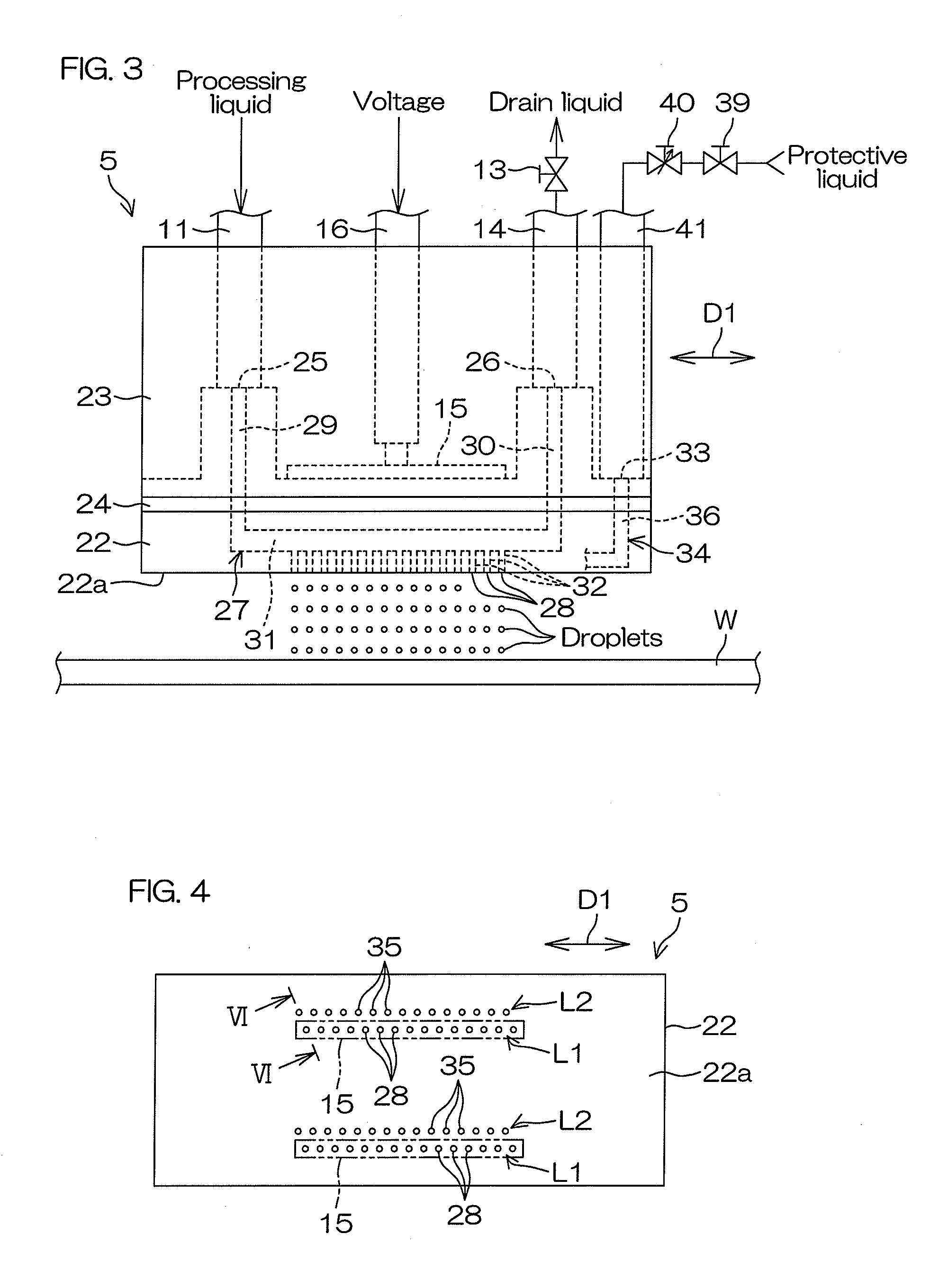
[0113]FIG. 9 is a plan view for describing a positional relationship between injection ports 28 and a discharge port 35 according to a second preferred embodiment of the present invention. In FIG. 9, component portions corresponding to respective portions indicated in FIG. 1 to FIG. 7 and FIG. 8A to FIG. 8D described above are provided with the same reference symbols as in FIG. 1, etc., and description thereof shall be omitted.

[0114]A principal point of difference of the second preferred embodiment with respect to the first preferred embodiment is that a single discharge port 35 corresponds to the plurality of injection ports 28.

[0115]Specifically, an injection nozzle 505 (injection unit, liquid film forming unit) includes a plurality of the injection ports 28 and a plurality of the discharge ports 35. As in the first preferred embodiment, the injection direction Q1 (see FIG. 6) and the discharge direction Q2 (see FIG. 6) are parallel directions and the positional relationship of th...

third preferred embodiment

[0118]FIG. 10 is a plan view for describing a positional relationship between injection ports 28 and a discharge port 35 according to a third preferred embodiment of the present invention. In FIG. 10, component portions corresponding to respective portions indicated in FIG. 1 to FIG. 9 described above are provided with the same reference symbols as in FIG. 1, etc., and description thereof shall be omitted.

[0119]A principal point of difference of the third preferred embodiment with respect to the second preferred embodiment is that the positional relationship of the injection ports 28 and the discharge port 35 is different.

[0120]Specifically, an injection nozzle 605 (injection unit, liquid film forming unit) includes a plurality of the injection ports 28 and a plurality of the discharge ports 35. As in the second preferred embodiment, in the third preferred embodiment, a single discharge port 35 corresponds to a plurality of injection ports 28. As in the first preferred embodiment, t...

fourth preferred embodiment

[0123]In accordance with another aspect of the present invention, a nozzle for making droplets collide with a substrate covered by a liquid film may have an arrangement exemplified by a fourth preferred embodiment described below.

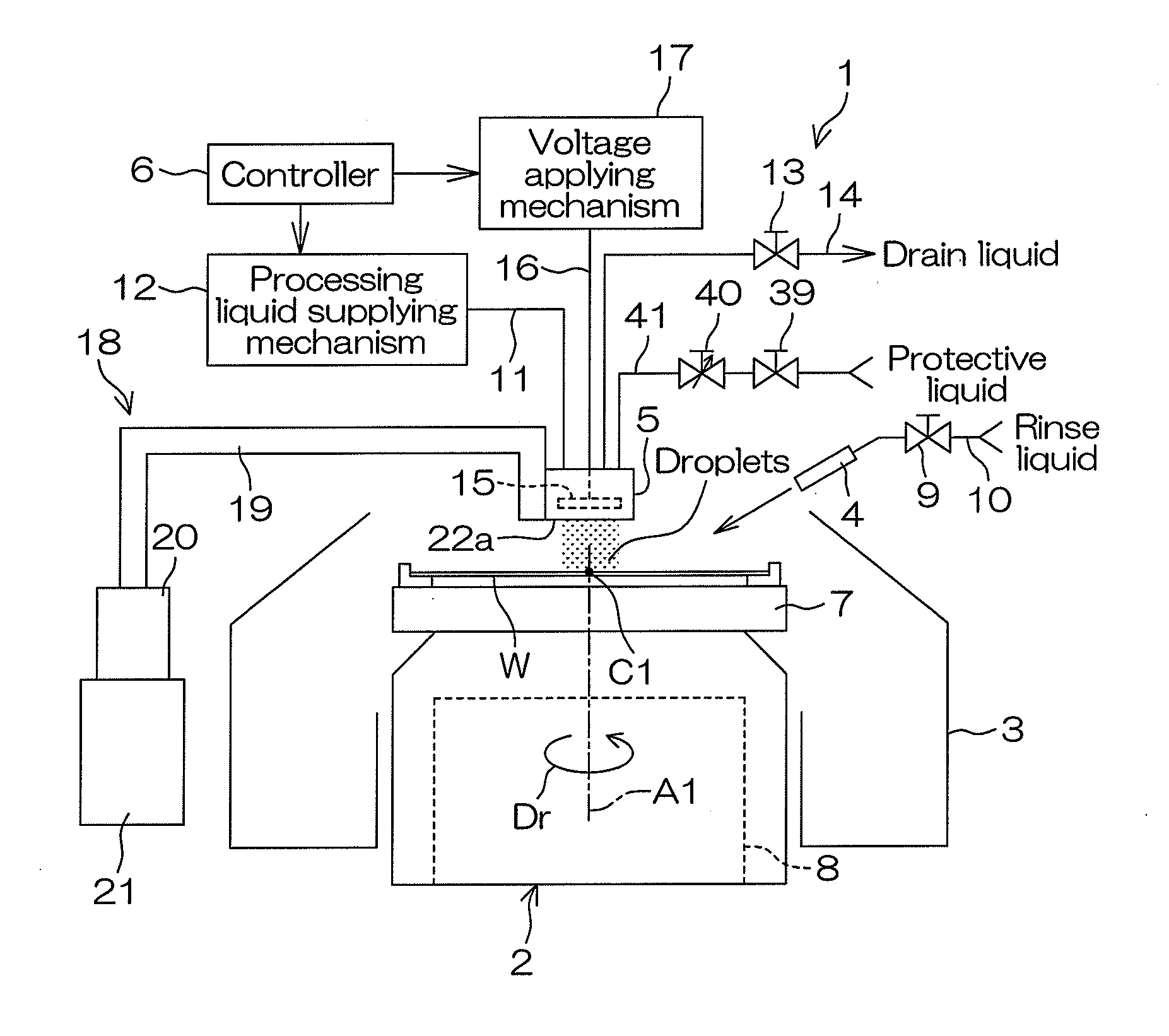
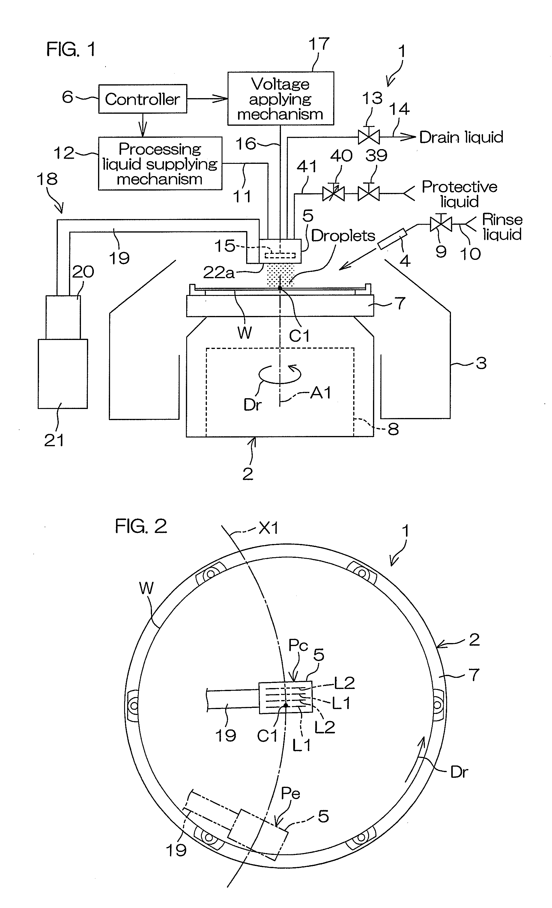
[0124]FIG. 11 is a schematic view of a general arrangement of a substrate processing apparatus 401 according to the fourth preferred embodiment of the present invention. FIG. 12 is a plan view of a cleaning nozzle 105 and an arrangement related thereto according to the fourth preferred embodiment of the present invention.

[0125]The substrate processing apparatus 401 is a one-by-one type substrate processing apparatus that processes a semiconductor wafer or other circular substrate W one at a time. As shown in FIG. 11, the substrate processing apparatus 401 includes a spin chuck 402 (substrate holding unit, substrate rotating unit) that horizontally holds and rotates the substrate W, a tubular cup 403 surrounding the spin chuck 402, a rinse liquid nozzle 404 ...


PUM

PropertyMeasurementUnit
Forceaaaaaaaaaa
Distanceaaaaaaaaaa
Circumferenceaaaaaaaaaa

Abstract

A substrate processing apparatus includes a substrate holding unit that holds a substrate, an injection unit that injects droplets of a processing liquid from a plurality of injection ports respectively toward a plurality of collision positions within a principal surface of the substrate held by the substrate holding unit, and a liquid film forming unit. The liquid film forming unit discharges a protective liquid from a plurality of discharge ports respectively toward a plurality of liquid contact positions within the principal surface of the substrate held by the substrate holding unit to form a plurality of liquid films of the protective liquid that respectively cover different collision positions.

Description

BACKGROUND OF THE INVENTION[0001]1. Field of the Invention[0002]The present invention relates to a substrate processing apparatus and a substrate processing method for processing a substrate, and a nozzle that makes droplets collide with a substrate covered by a liquid film. Examples of substrates to be processed include semiconductor wafers, substrates for liquid crystal displays, substrates for plasma displays, substrates for FEDs (Field Emission Displays), substrates for optical disks, substrates for magnetic disks, substrates for magneto-optical disks, substrates for photomasks, ceramic substrates, and substrates for solar cells.[0003]2. Description of Related Art[0004]In a manufacturing process for a semiconductor device or a liquid crystal display, etc., a substrate processing apparatus is used to process substrates, such as semiconductor wafers, glass substrates for liquid crystal displays. A substrate processing apparatus described in Japanese Unexamined Patent Application P...

Claims


Application Information

Patent Timeline
IPC IPC(8): B05C5/00B05D1/02B05B1/00B05C11/00
CPCB05B13/0228B05B17/0607B05C11/08H01L21/6715H01L21/67051H01L21/02H01L21/302B05B1/02B05B3/02
Inventor MAEGAWA, TADASHIARAKI, HIROYUKI
Owner SCREEN HLDG CO LTD
Why Eureka
Try Eureka