
Composite structure having an embedded sensing system

a sensing system and composite structure technology, applied in the field of composite structures, can solve the problems of different physical properties of the composite structure, and achieve the effect of enhancing the non-linear optical properties of the optical fiber

Inactive Publication Date: 2013-02-28
THE BOEING CO
View PDF20 Cites 28 Cited by
  • Summary
  • Abstract
  • Description
  • Claims
  • Application Information

AI Technical Summary

Benefits of technology

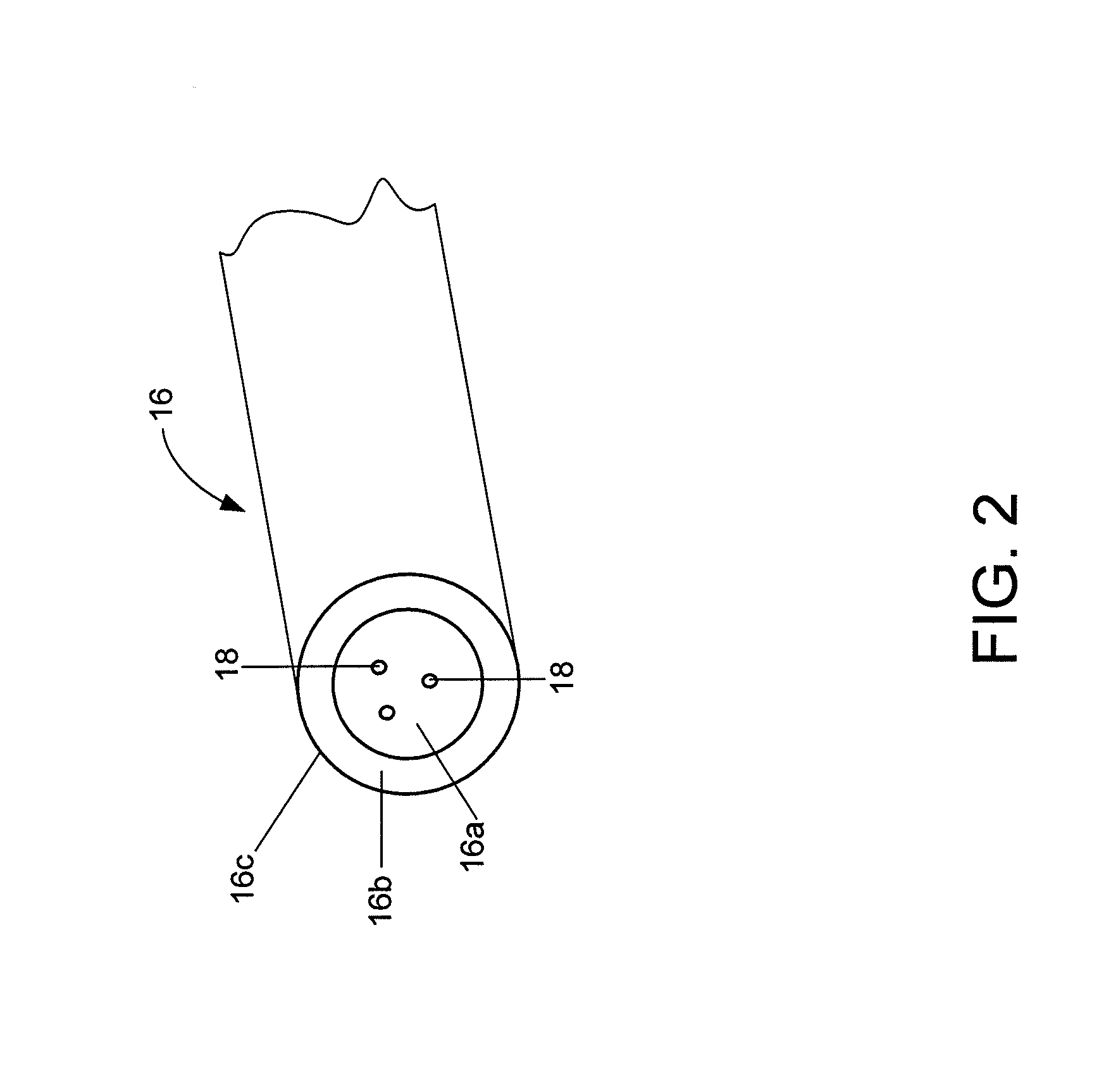
The patent describes a system for monitoring the health of a composite structure by using an optical fiber embedded in the structure and containing quantum dots that enhance the non-linear optical properties of the fiber. The quantum dots create a non-linear effect that can be detected when a defect occurs in the composite material, allowing for early detection and repair of potential issues. The system includes a detector that detects the non-linear effect and signals propagated through the optical fiber. The use of quantum dots in the optical fiber makes it more sensitive to defects and allows for stronger interaction with the surrounding resin. The system can provide reliable detection of defects and facilitate further inspection or repair of the composite material.

Problems solved by technology

While these inspection techniques may detect a number of anomalies, such as ply delaminations, other anomalies that may be created by the misorientation or misplacement of the structural fibers within the resin of a composite structure may present more of a challenge from a detection standpoint.
In some instances, however, the structural fibers or other elements within a composite structure may assume a different and an unintended orientation or position which may cause the physical properties of the composite structure to also be different.

Method used


Image

  • Composite structure having an embedded sensing system
  • Composite structure having an embedded sensing system
  • Composite structure having an embedded sensing system

Examples


Embodiment Construction

[0018]Embodiments of the present disclosure now will be described more fully hereinafter with reference to the accompanying drawings, in which some, but not all embodiments are shown. Indeed, these embodiments may be embodied in many different forms and should not be construed as limited to the embodiments set forth herein; rather, these embodiments are provided so that this disclosure will satisfy applicable legal requirements. Like numbers refer to like elements throughout.

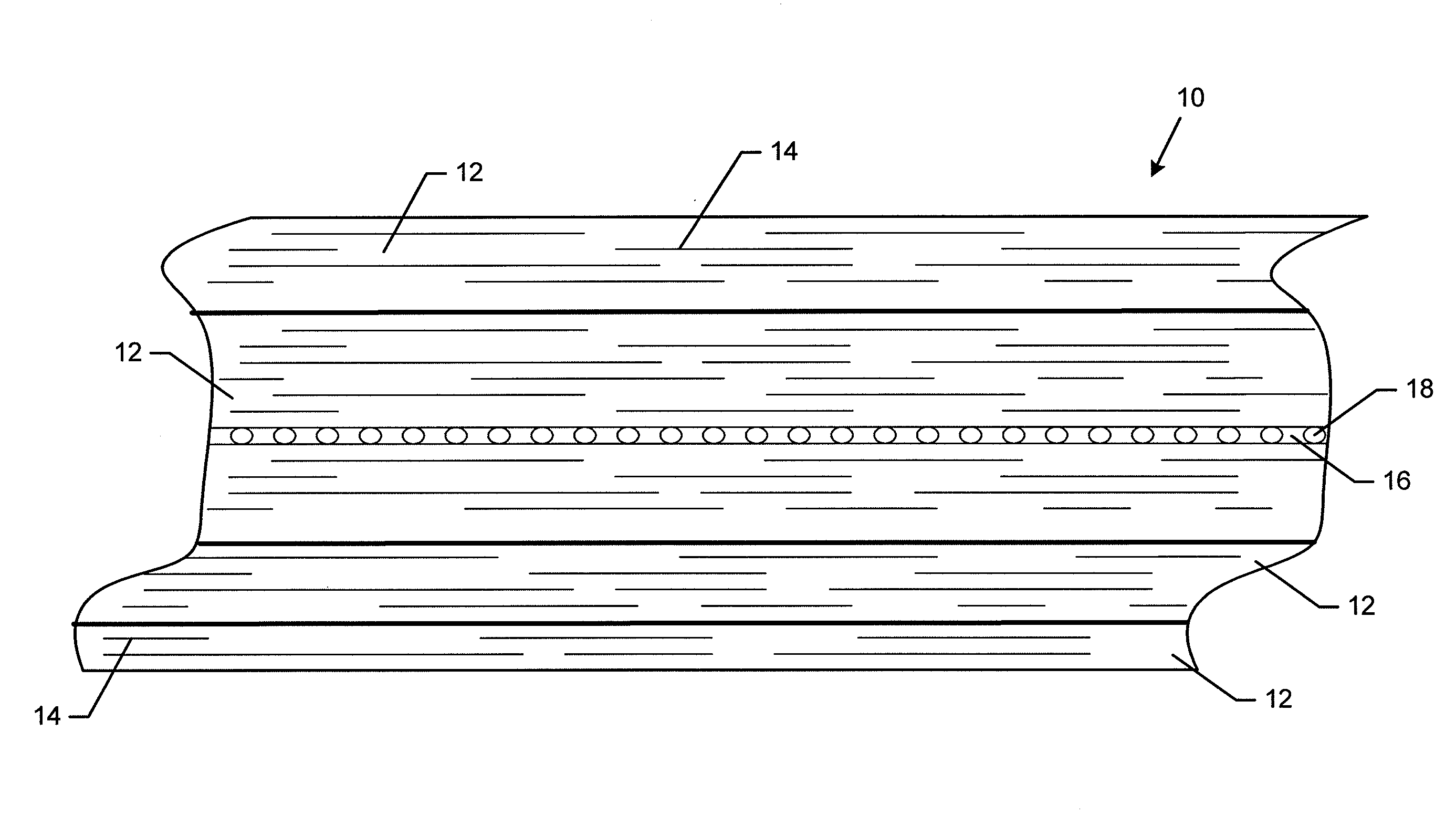
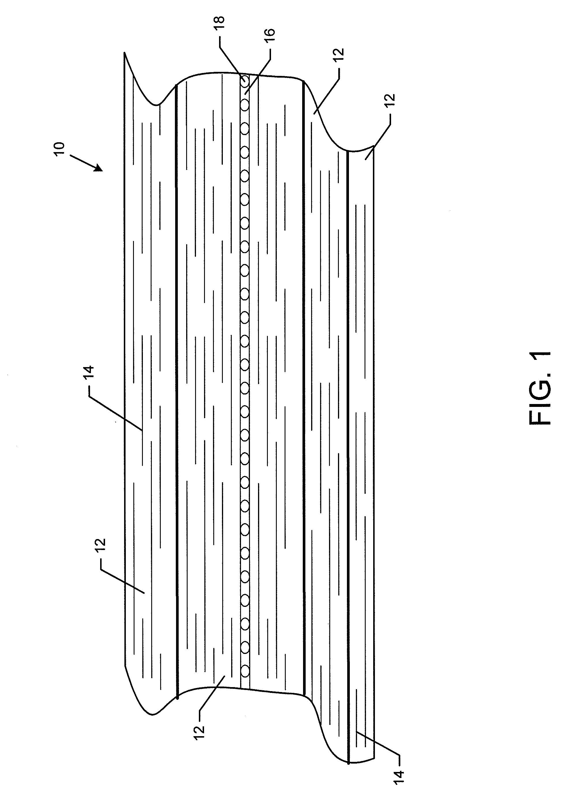
[0019]Referring now to FIG. 1, a composite structure 10 having an embedded sensing system in accordance with one embodiment of the present disclosure is illustrated. The composite structure 10 may be utilized in a variety of applications including in air vehicles, such as aircraft, spacecraft or the like, land vehicles, such as automobiles, trucks, trailers, bicycles, etc., marine vehicles, buildings and other structures. As shown in FIG. 1, the composite structure 10 includes a composite material having a plura...


PUM

PropertyMeasurementUnit
nonlinear optical propertiesaaaaaaaaaa
strength-aaaaaaaaaa
to-weight aaaaaaaaaa

Abstract

A composite structure having an embedded sensing system is provided, along with corresponding systems and methods for monitoring the health of a composite structure. The composite structure includes composite material and an optical fiber disposed within the composite material. The optical fiber includes a plurality of quantum dots for enhancing its non-linear optical properties. The quantum dots may be disposed in the core, in the cladding and / or on the surface of the optical fiber. The optical fiber is configured to support propagation of the signals and to be sensitive to a defect within the composite material. The quantum dots create a non-linear effect, such as a second order effect, in response to the defect in the composite material. Based upon the detection and analysis of the signals including the non-linear effect created by the quantum dots, a defect within the composite material may be detected.

Description

TECHNOLOGICAL FIELD[0001]Embodiments of the present disclosure relate generally to composite structures and, more particularly, to composite structures having embedded sensing systems for monitoring the health of a composite material.BACKGROUND[0002]Composite structures are structures consisting of two or more components often with some imparted order which are utilized in a wide variety of applications. For example, air vehicles, such as aircraft, spacecraft or the like, may utilize composite structures in order to take advantage of the benefits attributable to the increased strength-to-weight ratio offered by composite materials. Other applications that may include composite structures include other types of vehicles, such as automobiles, marine vehicles, bicycles and the like, as well as a wide variety of other structures, such as buildings, bridges, etc. Composite structures may also be produced and used with additional functionalities including altered thermal, electrical, acou...

Claims


Application Information

Patent Timeline
Patent Type & Authority Applications(United States)
IPC IPC(8): G01N21/88G02B6/00B82Y15/00B82Y20/00
CPCG01N21/8422G01N2021/8472B82Y15/00B82Y20/00G01L1/242B82Y30/00G02F2202/108G01L1/246G02F1/3556G02F1/365G02F1/377G02F2201/02G01D5/3538
Inventor HUNT, JEFFREY H.BELK, JOHN H.
Owner THE BOEING CO
Learn More