Fixation system for orthopedic devices

a technology for fixing systems and orthopedic devices, applied in the field of fixing systems, can solve the problems of reducing the structural integrity of the bone, limiting the options for securing the orthopedic implant, and preventing securely re-attaching the orthopedic fastener in the bone, so as to facilitate the subsequent removal of the orthopedic implant

Inactive Publication Date: 2013-02-21
RDC HLDG
View PDF1 Cites 10 Cited by
  • Summary
  • Abstract
  • Description
  • Claims
  • Application Information

AI Technical Summary

Benefits of technology

The present patent is about an orthopedic implant system that provides surgeons with additional flexibility during the implantation procedure or a revision procedure without compromising the structural integrity of the implant. The system includes an expandable member that is inserted through the lumen of the implant and positioned in the cancellous bone near the distal portion of the implant. A flowable biomaterial is delivered to the expandable member to secure the implant in the bone. The expanded configuration of the expandable member includes at least one dimension greater than a corresponding dimension on the implant. An insert is secured in the lumen to releasably attach the fixation system to the implant, such that the expandable member is detachable from the implant to facilitate subsequent removal of the implant from the bone. The technical effect of this patent is to provide a more effective and flexible method for implanting orthopedic implants in bones.

Problems solved by technology

If the bone at the implantation site is compromised, either before, such as due to osteoporosis, or as a result of the implantation procedure, the surgeon may have limited options for securing the orthopedic implant.
Loosening and backing out of an orthopedic fasteners can result in decreased structural integrity of the bone.
Once an orthopedic fastener manages to work itself loose, wear and tear to the opening or space in the bone within which it was received may prohibit securely refastening the orthopedic fastener in the bone.
Adding more orthopedic fasteners to compensate for the compromised bone complicates future revision or removal, and may further weaken the bone.
For example, the formation of screw holes in the cortical bone provides stress risers that substantially increases the risk of bone re-fracture.
Cement induced osteolysis or necrotic bone may impair the fixation and lead to eventual fastener loosening and failure.
In the case of failure it is often difficult to remove cement from the bone and it is usually associated with excessive damage to the surrounding bone.
Bone cement at the interface with the orthopedic fasteners greatly complicates this procedure.

Method used


Image

  • Fixation system for orthopedic devices
  • Fixation system for orthopedic devices
  • Fixation system for orthopedic devices

Examples


example 1

[0175]Four identical fasteners were tested according ASTM standard F543-02 Annex A3 “Test Method for Determining the Axial Pullout Strength of Medical Bone Screws. The test was performed on a solid rigid polyurethane foam 40 millimeters×130 millimeters×180 millimeters block with a density of 20 pounds made according to Specification F1839, purchased from www.sawbones.com as product number 1522-03.

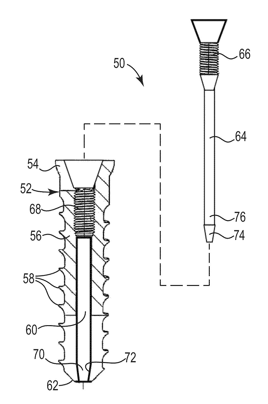
[0176]The fasteners had an outside diameter of about 9.0 millimeters with an outside threaded length of about 17 millimeters. The lumen had an inside diameter of about 6.0 millimeters.

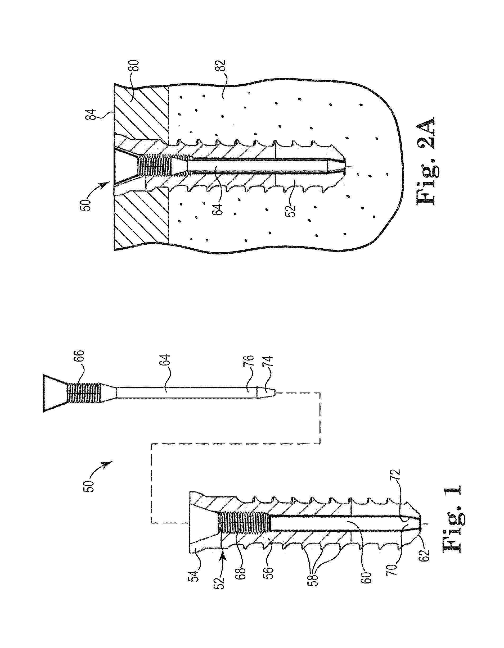
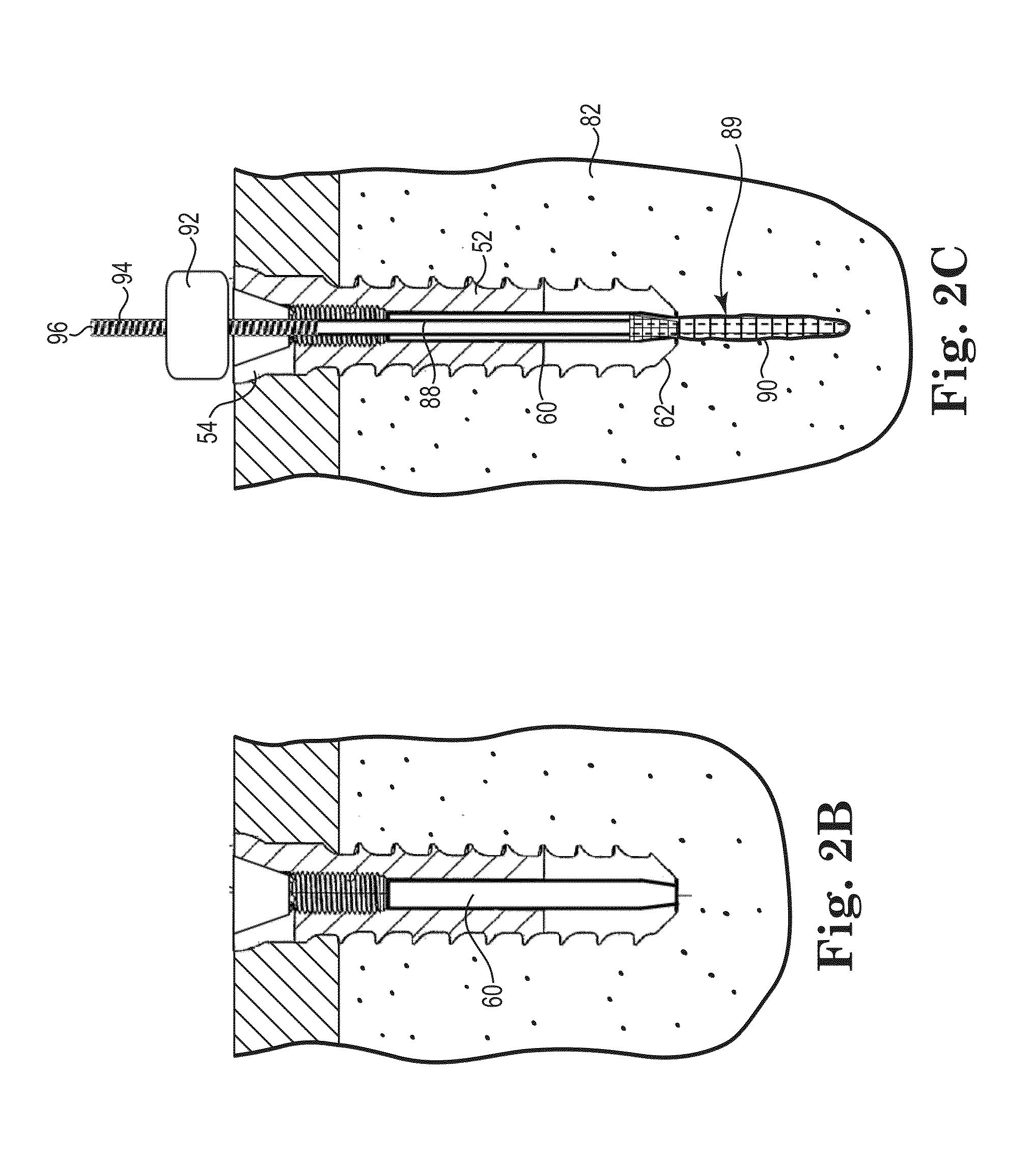
[0177]Four pilot holes about 8.0 millimeters in diameter were drilled completely through the test block. A fastener was secured in each of the pilot holes. A cavity was formed behind the fasteners for Samples C and D using a wire with a bent tip attached to a cordless drill and inserted through the lumen of the fasteners. The drill was run at a moderate speed for about 20 seconds for each Sample.

[0178]Samples ...

example 2

[0183]Four fasteners were tested according ASTM standard F543-02 Annex A3 “Test Method for Determining the Axial Pullout Strength of Medical Bone Screws, to evaluate a fixation structure having a ribbon shape.

[0184]The test was performed on a solid rigid polyurethane foam 40 millimeters x 130 millimeters x 180 millimeters block with a density of 20 pounds made according to Specification F1839, purchased from www.sawbones.com as product number 1522-03.

[0185]Pilot holes for Samples E and F had a diameter of about 6.3 millimeters and pilot holes for Samples G and H had a diameter of about 4.5 millimeters.

[0186]The fasteners for Samples E and F had an outside diameter of about 6.0 millimeters with an outside threaded length of about 11.0 millimeters. The lumen had an inside diameter of about 5.0 millimeters.

[0187]The fasteners for Samples G and H had an outside diameter of about 5.0 millimeters with an outside threaded length of about 9.0 millimeters. The lumen had an inside diameter of...

example 3

[0192]Three fasteners were tested according ASTM standard F543-02 Annex A3 “Test Method for Determining the Axial Pullout Strength of Medical Bone Screws, to evaluate a fixation structure having a ribbon shape.

[0193]The test was performed on a solid rigid polyurethane foam 40 millimeters x 130 millimeters x 180 millimeters block with a density of 20 pounds made according to Specification F1839, purchased from www.sawbones.com as product number 1522-03.

[0194]Pilot holes for Samples I, J, and K with a diameter of about 6.0 millimeters were drilled into the test block at a depth of about 2x the length of the fasteners, about 22 millimeters.

[0195]The fasteners for Samples I, J, and K had an outside diameter of about 6.0 millimeters with an outside threaded length of about 11.0 millimeters. The lumen had an inside diameter of about 5.0 millimeters.

[0196]A cavity was formed behind the fasteners for Samples J and K using a bent wire attached to a cordless drill inserted through the lumen o...


PUM


Abstract

A fixation system configured to releasably secure an orthopedic implant to a bone. The fixation system including at least one expandable member that is inserted through the lumen and positioned in cancellous bone near the distal portion of the orthopedic implant. A delivery tube delivers a flowable biomaterial to the expandable member. The expand fixation structure includes at least one dimension greater than a corresponding dimension on the orthopedic implant to secure the orthopedic implant in the bone. An insert is secured in the lumen to releasably attach the fixation system to the orthopedic implant. The expandable member is detachable from the orthopedic implant to facilitate subsequent removal of the orthopedic implant from the bone.

Description

RELATED APPLICATIONS[0001]The present application is a continuation-in-part of PCT application PCT / US12 / 43346, entitled System and Method for Repairing Joints filed Jun. 20, 2012, which claims the benefit of U.S. Provisional Application No. 61 / 498,687, entitled Orthopedic Fixation System and Method of Use, filed Jun. 20, 2011; U.S. Provisional Application No. 61 / 515,009, entitled Orthopedic Fixation System and Method of Use, filed Aug. 4, 2011; and U.S. Provisional Application No. 61 / 591,304, entitled Fixation System and Method for Repairing Joints, filed Jan. 27, 2012, the disclosures of which are hereby incorporated by reference.FIELD OF THE INVENTION[0002]The present disclosure is directed to a fixation system used to supplement the fixation of an orthopedic implant. The fixation system includes a fixation structure that is releasably secured to the orthopedic implant and embedded in cancellous bone by a biomaterial. The biomaterial is preferably a resorbable, bone-growth stimula...

Claims


Application Information

Patent Timeline
IPC IPC(8): A61B17/84
CPCA61F2/0811A61F2002/087A61F2002/0841
Inventor SCHWAPPACH, KARL G.
Owner RDC HLDG
Why Eureka
Try Eureka