
Providing safety status information

a technology of safety status and information, applied in the field of computing systems, can solve the problems of direct cost, indirect cost, and serious loss of life in emergencies, and achieve the effect of reducing the number of deaths

Active Publication Date: 2013-02-14
THE SAFETY NETWORK PARTNERSHIP LLC
View PDF2 Cites 32 Cited by
  • Summary
  • Abstract
  • Description
  • Claims
  • Application Information

AI Technical Summary

Benefits of technology

The present invention relates to a computing system and method for improving emergency preparedness and response phase communication during emergency situations. The invention aims to address the complexity and impact of emergencies by providing individuals with relevant and effective emergency preparedness information and facilitating communication of such information during the response phase. The invention utilizes a computing system and user device to process data and store it as emergency preparedness information and response phase communications information. The invention also includes a method for acquiring safety status information associated with a set of user devices. Overall, the invention improves the effectiveness of emergency preparedness and response by providing relevant and effective information to individuals and facilitating communication of such information.

Problems solved by technology

Emergencies are known to be associated with direct costs (e.g., rebuilding), indirect costs (e.g., higher insurance premiums,) and serious loss of life.
Despite such access, individuals may not always obtain desired or optimal emergency preparedness information due to complexities associated with a relevant emergency scenario, resource gaps, chain of command, lack of training, and tension associated with emergency.
Despite such utilization, public computing systems (e.g., a commercial wireless carrier network) typically can't sustain a demanded traffic volume of such response phase communications information when the demanded traffic volume is multiples of a typical non-emergency time period.

Method used


Image

  • Providing safety status information
  • Providing safety status information
  • Providing safety status information

Examples


Embodiment Construction

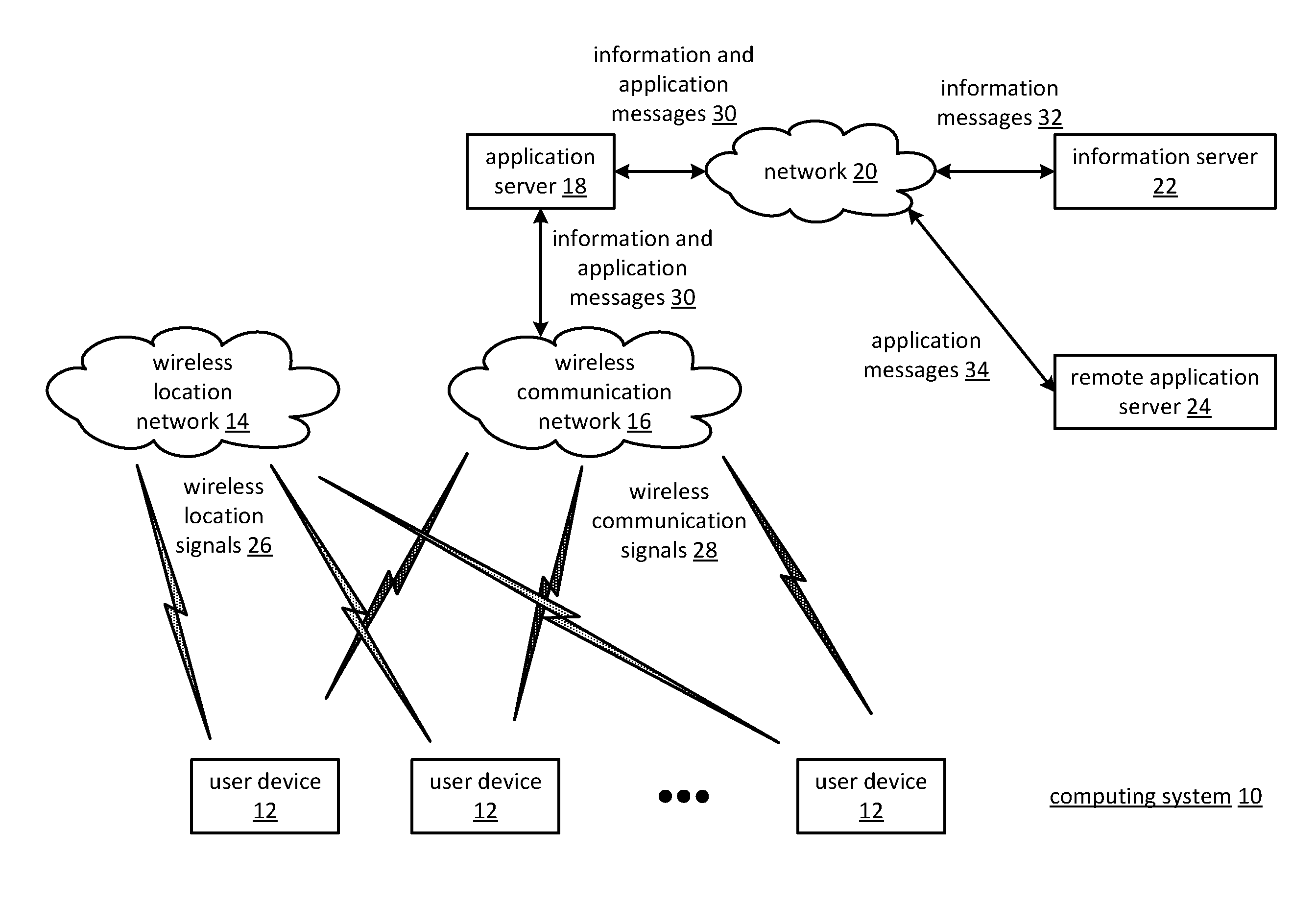
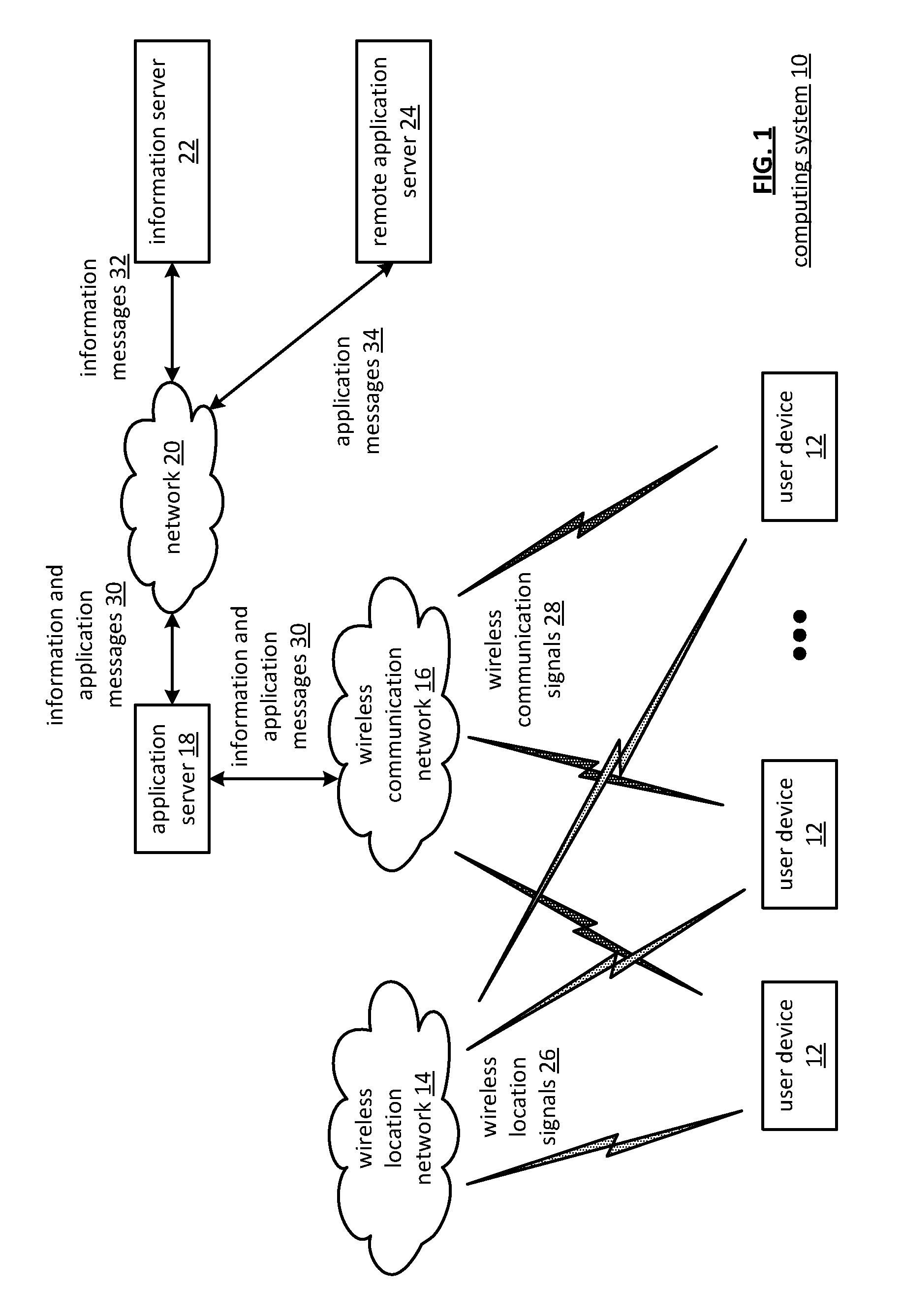
[0019]FIG. 1 is a schematic block diagram of an embodiment of a computing system 10 that includes a plurality of user devices 12, a wireless location network 14, a wireless communication network 16, an application server 18, a network 20, an information server 22, and a remote application server 24. The wireless location network 14 includes one or more of a public wireless location system (e.g., global positioning satellite (GPS), a cellular network) and one or more private wireless location systems (e.g., wireless beacon, a wireless local area network (WLAN)). The wireless location network 14 sends wireless location signals 26 to the plurality of user devices 12 to enable determination of location information.

[0020]The wireless communications network 16 includes one or more of a public wireless communications system and a private wireless communications system and may operate in accordance with one or more wireless industry standards including universal mobile telecommunications sy...


PUM


Abstract

A method begins by a processing module receiving a safety status request for a safety status level associated with a user device and determining whether to generate a safety status response. When generating a safety status response, the method continues with the processing module obtaining the safety status level associated with the user device and determining whether to include location information in the safety status response. When including the location information, the method continues with the processing module obtaining location coordinates corresponding to the user device, obtaining street address location information based on the location coordinates, generating the location information based on the location coordinates and the street address location information, generating the safety status response to include the safety status level and the location information, and outputting the safety status response to a requesting entity.

Description

CROSS REFERENCE TO RELATED PATENTS[0001]This patent application is claiming priority under 35 U.S.C. §119(e) to a provisionally filed patent application entitled, “EMERGENCY PREPAREDNESS STATUS PROCESSING”, having a provisional filing date of Aug. 9, 2011, and a provisional Ser. No. 61 / 521,506, pending, which is incorporated herein by reference in its entirety and made part of the present U.S. Utility patent application for all purposes.STATEMENT REGARDING FEDERALLY SPONSORED RESEARCH OR DEVELOPMENT[0002]NOT APPLICABLEINCORPORATION-BY-REFERENCE OF MATERIAL SUBMITTED ON A COMPACT DISC[0003]NOT APPLICABLEBACKGROUND OF THE INVENTION[0004]1. Technical Field of the Invention[0005]This invention relates generally to computing systems and more particularly to emergency preparedness information processing within such computing systems.[0006]2. Description of Related Art[0007]Emergencies are known to be associated with direct costs (e.g., rebuilding), indirect costs (e.g., higher insurance p...

Claims


Application Information

Patent Timeline
Patent Type & Authority Applications(United States)
IPC IPC(8): H04W4/02H04W4/14H04M1/72421H04W4/90
CPCH04W8/22H04L12/1895H04W4/22H04W4/90H04W4/023H04W4/021H04M1/72421H04L51/52H04L51/222H04W8/183H04W8/186
Inventor GRUBE, GARY W.QUISENBERRY, EVAN EDWARDBUCHALO, JOHN EDWARD
Owner THE SAFETY NETWORK PARTNERSHIP LLC
Learn More