
Transmission mode adaptation in a wireless network

a wireless network and transmission mode technology, applied in the direction of signal quality detector error detection/prevention, transmission monitoring, line-transmission details, etc., can solve the problem of not maximizing the actual pusch throughput, measurement (srs for lte ul) may experience a different power level compared, and the selection of precoders is subject to inter-antenna imbalance variation, etc. problem, to achieve the effect of facilitating the selection of precoders

Inactive Publication Date: 2013-01-31
TELEFON AB LM ERICSSON (PUBL)
View PDF5 Cites 22 Cited by
  • Summary
  • Abstract
  • Description
  • Claims
  • Application Information

AI Technical Summary

Benefits of technology

The present invention improves the chances of selecting the transmission mode that maximizes actual throughput, leading to better performance than conventional methods.

Problems solved by technology

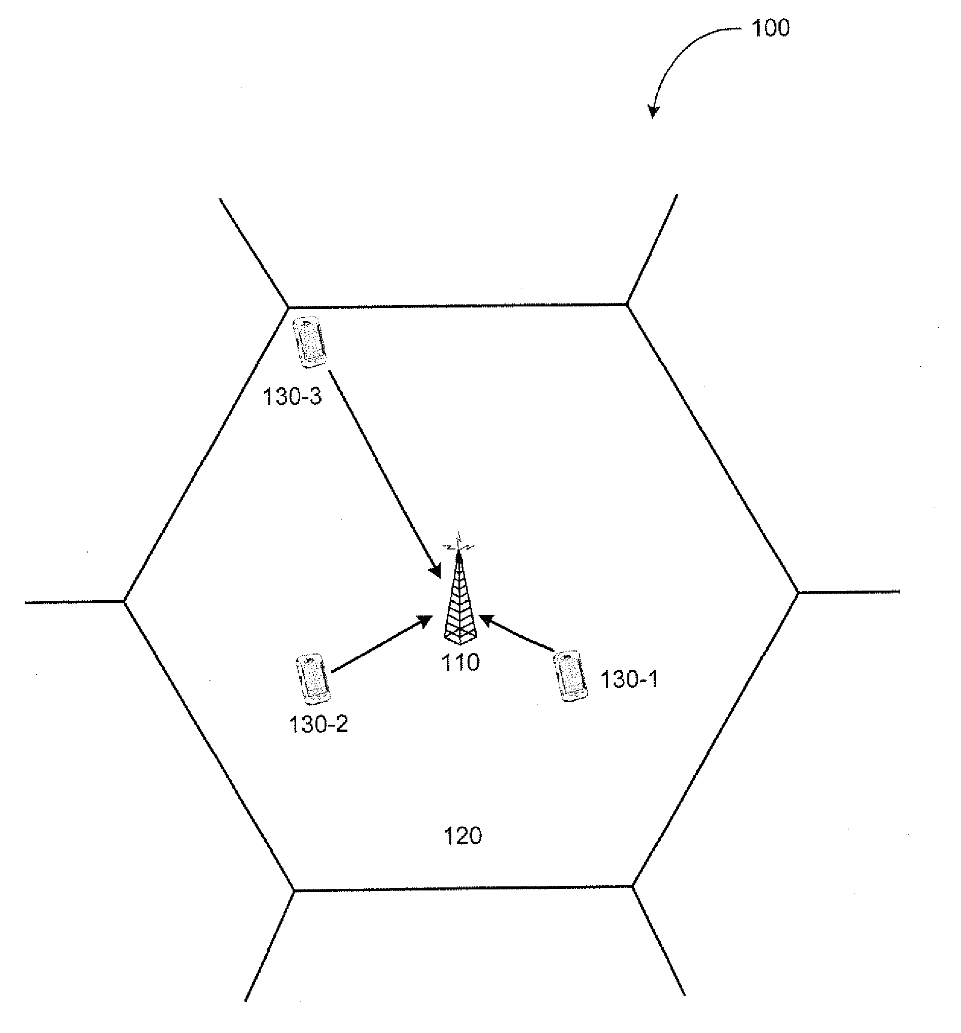
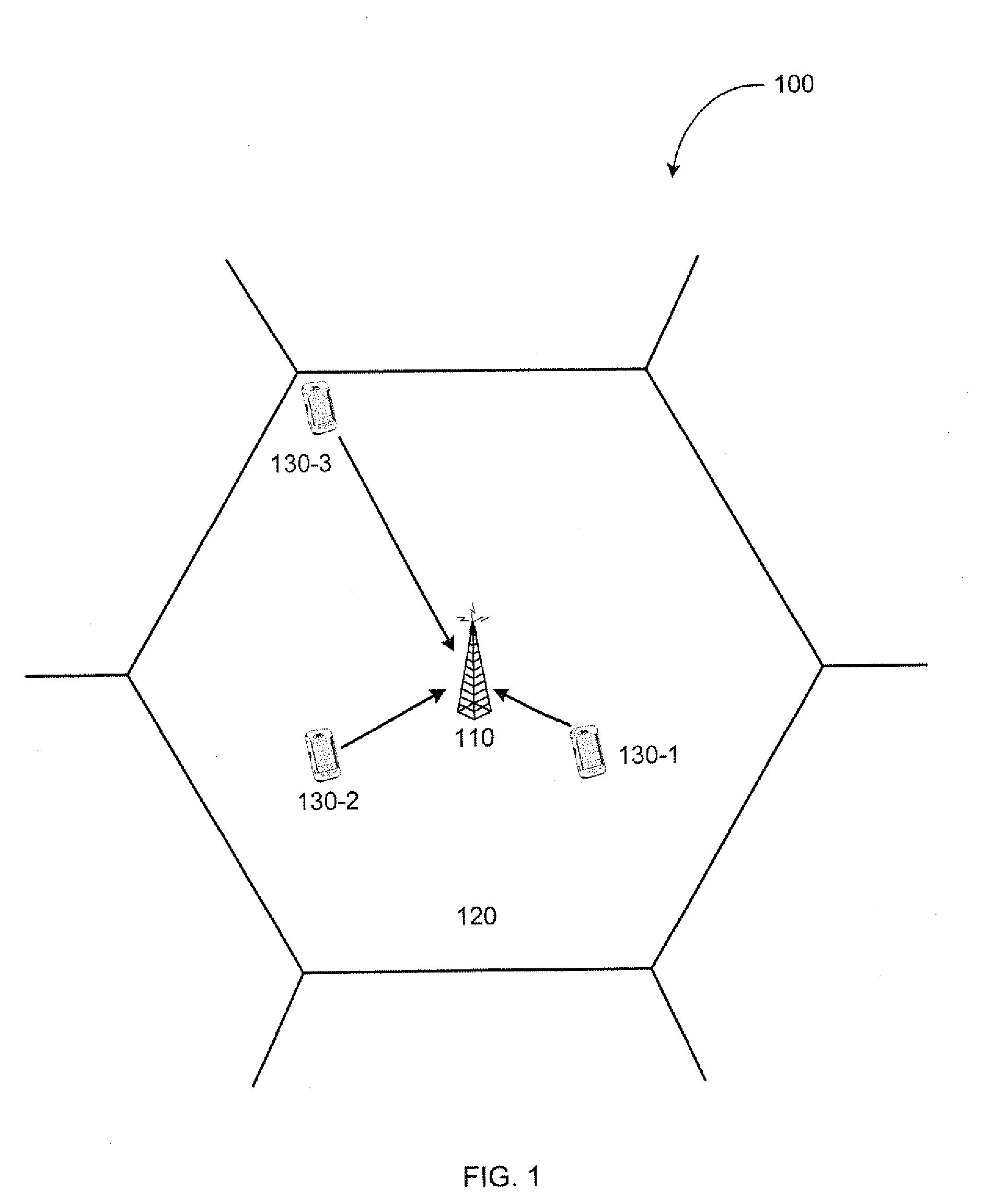
But it should be understood that precoder selection is subject to inter-antenna imbalance variation between measurement period and actual data transmission period.
One problem of conventional transmission mode adaptation is that measurement (SRS for LTE UL) may experience a different power level compared to that of an actual data reception (PUSCH for LTE UL).
As a result, the receiver may end up selecting a precoder that does not maximize the actual PUSCH throughput.
However, in the presence of gain increase, only one or some precoders may maximize the actual throughput.

Method used


Image

  • Transmission mode adaptation in a wireless network
  • Transmission mode adaptation in a wireless network
  • Transmission mode adaptation in a wireless network

Examples


Embodiment Construction

[0026]For purposes of explanation and not limitation, specific details are set forth such as particular architectures, interfaces, techniques, and so on. However, it will be apparent to those skilled in the art that the technology described herein may be practiced in other embodiments that depart from these specific details. That is, those skilled in the art will be able to devise various arrangements which, although not explicitly described or shown herein, embody the principles of the described technology.

[0027]In some instances, detailed descriptions of well-known devices, circuits, and methods are omitted so as not to obscure the description with unnecessary details. All statements herein reciting principles, aspects, embodiments and examples are intended to encompass both structural and functional equivalents. Additionally, it is intended that such equivalents include both currently known equivalents as well as equivalents developed in the future, i.e., any elements developed t...


PUM


Abstract

Conventional mode adaptation does not account for the gain imbalance between channels for measurement and for data reception. Therefore, the precoder, which is selected based on the measurement channel, may not be the optimal precoder for the data reception channel. By maintaining relative SINR ordering between transmission modes, a receiver may select the transmission mode for a transmitter that maximizes the actual throughput even in the presence of inter-antenna gain increase or decrease.

Description

TECHNICAL FIELD[0001]Technical field of present disclosure relates to transmission mode adaptation in a node of a wireless network. In particular, the field is related to selecting a transmission mode among a plurality of transmission modes for the node of the wireless network in the presence of gain variation.BACKGROUND AND SUMMARY[0002]Currently, MIMO (multiple-input-multiple-output) is considered to be a key element of the air interface for high-speed wireless communications. MIMO can provide both diversity gain and multiplexing gain. MIMO enables simultaneous transmission of multiple streams, each stream being referred to as a layer. The number of transmit antennas, receive antennas, and layers are denoted by NT, NR, and R, respectively. The number of layers R is never greater than the number of transmit antennas NT, and is often smaller than or equal to the number of receive antennas NR.[0003]Generally, MIMO assumes the use of a precoder, which is mathematically expressed as a ...

Claims


Application Information

Patent Timeline
IPC IPC(8): H04B17/00
CPCH04L1/0015H04L1/20H04B17/336H04L25/03929H04B7/0473H04L25/03923
Inventor PARK, CHESTERWANG, YI-PIN ERIC
Owner TELEFON AB LM ERICSSON (PUBL)
Learn More