
Method of producing lithium ion-storing/releasing material, lithium ion-storing/releasing material, and electrode structure and energy storage device using the material

a technology of lithium ion-storing/releasing material and electrode structure, which is applied in the direction of cell components, electrochemical generators, transportation and packaging, etc., can solve the problems of insufficient extent to which the problem is alleviated, and the cell performance is reduced. achieve high initial charge and discharge efficiency, high power density, and high energy density

Inactive Publication Date: 2012-12-20
CANON KK
View PDF3 Cites 15 Cited by
  • Summary
  • Abstract
  • Description
  • Claims
  • Application Information

AI Technical Summary

Benefits of technology

[0077]Another object of the present invention is to provide a material prepared by the above production method and capable of electrochemically storing or releasing a large amount of lithium ions, an electrode structure formed of the material, and an energy storage device provided with the electrode structure and having such a characteristic that a reduction in capacity is small even when charging and discharging are repeatedly performed, in conjunction with high power density and a high energy density.
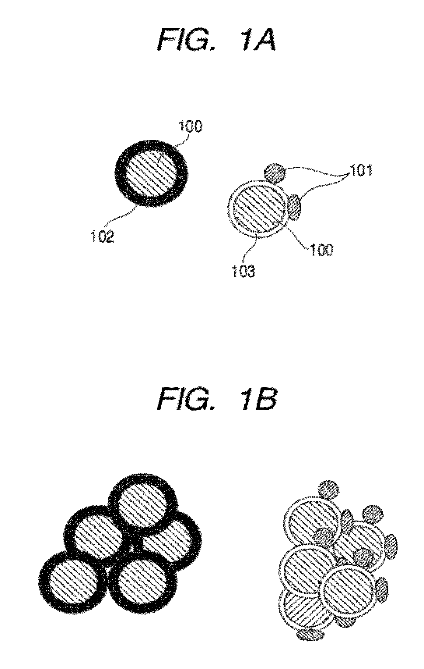
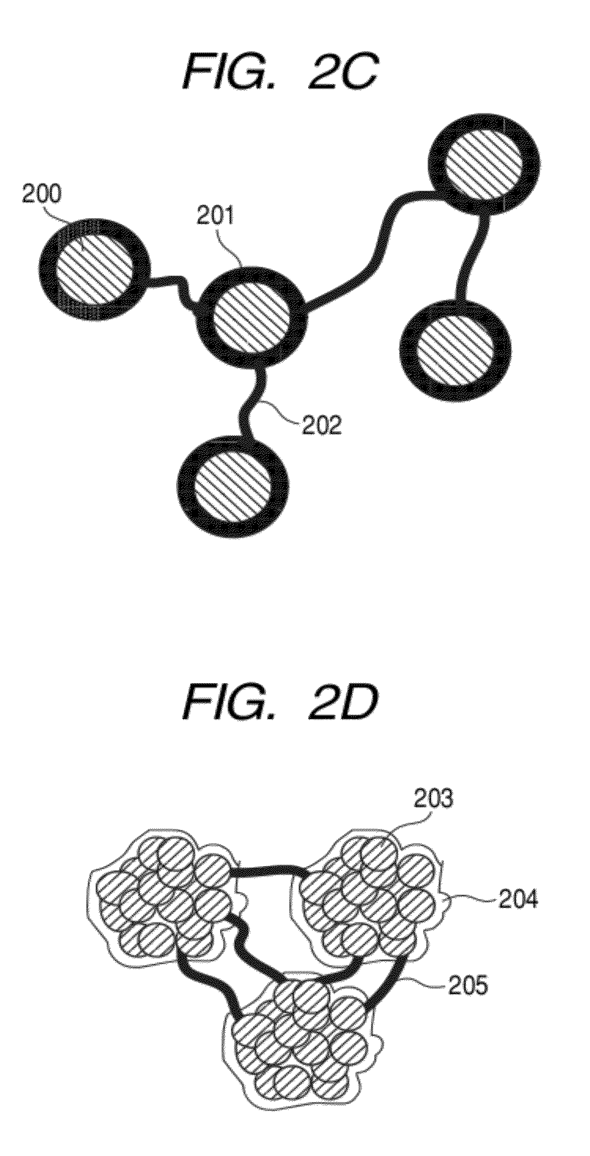
[0080]As a result of various experiments, the inventors of the present invention have found the following: the oxide of Si or Sn in particles formed of Si, Sn, or an alloy of any one of such elements is allowed to react with a metal so that a metal oxide stabler than the oxide of Si or Sn is produced, and the particles formed of Si, Sn, or an alloy of any one of such elements are coated with the metal oxide stabler than the oxide of Si or Sn, whereby the content of the oxide of Si or Sn can be reduced, and hence the oxidation of the particles formed of Si, Sn, or an alloy of any one of such elements can be suppressed, and the coulombic efficiency of a cell for the first charging and discharging can be improved. In addition, the inventors have found that an electrode produced by using an active material having a network structure made up from Si particles with fibrous (filamentous) substances each having a diameter of a nanometer to submicron size shows an additional improvement in durability.
[0082]It should be noted that Gibbs free energy at the time of producing a metal oxide by oxidation of a metal element included in the metal oxide or the metal is smaller than Gibbs free energy at the time of oxidizing silicon or tin, and the metal oxide has higher thermodynamic stability than silicon oxide or tin oxide.
[0091]According to the method of producing a lithium ion-storing / releasing material of the present invention, a material capable of electrochemically storing and releasing a large amount of lithium ions can be produced without using any complicated production step.
[0092]In addition, the energy storage device of the present invention utilizing the electrochemical oxidation-reduction reaction of lithium ions using the electrode structure of the present invention can provide high initial charge and discharge efficiency, high power density and high energy density, and the long cycle life of the device for charging and discharging can be ensured. In addition, the energy storage device thus obtained can be charged quickly.

Problems solved by technology

Si and Sn capable of electrochemically absorbing and releasing a large amount of Li has conventionally involved such problems that they show a large volume expansion at the time of the absorption of Li, and are turned into a fine powder by volume expansion or shrinkage due to the absorption or release of Li to increase the resistance of an electrode, and a reduction in performance of a cell occurs owing to the repetition of charging and discharging.
The problem referred to as the reduction in performance of the cell due to the repetition of charging and discharging has been alleviated by those approaches, but the extent to which the problem is alleviated is still insufficient.

Method used


Image

  • Method of producing lithium ion-storing/releasing material, lithium ion-storing/releasing material, and electrode structure and energy storage device using the material
  • Method of producing lithium ion-storing/releasing material, lithium ion-storing/releasing material, and electrode structure and energy storage device using the material
  • Method of producing lithium ion-storing/releasing material, lithium ion-storing/releasing material, and electrode structure and energy storage device using the material

Examples


examples

[0330]Hereinafter, the present invention will be described in more detail by way of examples.

[0331][Preparation of an Electrode Material (Active Material) for the Negative Electrode of the Energy Storage Device]

[0332]An example of a method of preparing a powder material to be used as an active material for the negative electrode of the energy storage device in the present invention will be given below.

[0333]Examples of Procedure for Preparation of Powder Material

[0334]Preparation by Thermal Plasma Method

[0335]Here, nanoparticles serving as a negative electrode material were synthesized with a radiofrequency (RF) inductively coupled thermal plasma-generating apparatus in accordance with the following procedure. The above inductively coupled thermal plasma-generating apparatus is constituted of a reactor connected with a vacuum pump and a thermal plasma torch. The thermal plasma torch is provided with a gas introducing portion for generating plasma and a raw material powder-introducin...

example tp1

[0336]The above radiofrequency (RF) inductively coupled thermal plasma-generating apparatus was used. First, the inside of the reactor was evacuated to a vacuum with the vacuum pump, and an argon gas and a hydrogen gas as gases for generating plasma were flowed at flow rates of 200 liters / min and 10 liters / min, respectively, and the total pressure of the gases was controlled to 50 kPa. A radiofrequency of 4 kHz was applied to the induction coil with an electric power of 80 kW so that plasma was generated. Next, a powder raw material obtained by mixing 97 parts by weight of a silicon powder having an average particle diameter of 4 μm and 3 parts by weight of zirconia having an average particle diameter of 1 μm was fed into the thermal plasma at a feeding rate of about 500 g / h together with an argon gas flowed at a flow rate of 15 liters / min as a carrier gas. The raw material was subjected to a reaction for a predetermined reaction time, whereby a fine powder material was obtained. Th...

example tp2

[0339]Nanoparticles were obtained by the same operations as in Example TP1 described above except that a powder raw material obtained by mixing 95 parts by weight of a silicon powder having an average particle diameter of 4 μm and 5 parts by weight of zirconia having an average particle diameter of 1 μm was used instead of the powder raw material obtained by mixing 97 parts by weight of a silicon powder having an average particle diameter of 4 μm and 3 parts by weight of zirconia having an average particle diameter of 1 μm.

[0340]FIG. 8 shows the high-resolution image of the resultant powder with a TEM.

[0341]In the high-resolution image with a TEM of FIG. 8, an amorphous phase having a thickness of 0.5 nm to 5 nm was observed on the surface of crystalline silicon having a diameter of 5 nm to 100 nm.

[0342]Comparison between the results of X-ray photoelectron spectroscopy (XPS) of Examples TP1 and TP2 (see FIG. 17) showed that the amount of silicon oxide of Example TP2 was small, and t...


PUM

PropertyMeasurementUnit
thicknessaaaaaaaaaa
diameteraaaaaaaaaa
lengthaaaaaaaaaa

Abstract

A method of producing a material capable of electrochemically storing and releasing a large amount of lithium ions is provided. The material is used as an electrode material for a negative electrode, and includes silicon or tin primary particles composed of crystal particles each having a specific diameter and an amorphous surface layer formed of at least a metal oxide, having a specific thickness. Gibbs free energy when the metal oxide is produced by oxidation of a metal is smaller than Gibbs free energy when silicon or tin is oxidized, and the metal oxide has higher thermodynamic stability than silicon oxide or tin oxide. The method of producing the electrode material includes reacting silicon or tin with a metal oxide, reacting a silicon oxide or a tin oxide with a metal, or reacting a silicon compound or a tin compound with a metal compound to react with each other.

Description

CROSS-REFERENCE TO RELATED APPLICATIONS[0001]This application is a continuation of International Application No. PCT / JP2008 / 066506, filed Sep. 8, 2008, which claims the benefit of Japanese Patent Applications No. 2007-232090, filed Sep. 6, 2007, and No. 2007-321373, filed Dec. 12, 2007.BACKGROUND OF THE INVENTION[0002]1. Field of the Invention[0003]The present invention relates to a method of producing a lithium ion-storing / releasing material mainly composed of a metal which alloys with lithium by an electrochemical reaction such as silicon or tin and a metal oxide, an electrode structure formed of the material, and an energy storage device having the electrode structure.[0004]2. Description of the Related Arts[0005]It has been pointed out that global warming may occur owing to a greenhouse effect because the amount of CO2 gas in the air has been recently increasing. In addition, air pollution due to, for example, CO2, NOR, and a hydrocarbon exhausted from automobiles is of serious ...

Claims


Application Information

Patent Timeline
Patent Type & Authority Applications(United States)
IPC IPC(8): H01M4/48H01M4/64D01F9/08B82Y30/00B82Y99/00H01G11/06H01G11/22H01G11/30H01M4/134H01M4/36H01M4/38H01M4/58H01M10/052H01M10/36
CPCH01G11/46H01M4/134H01M4/366H01M4/48H01M4/58H01M4/62H01M10/0525H01G11/24H01G11/50Y02E60/13H01M4/386H01M4/387Y10T428/259Y10T428/2927Y02E60/10
Inventor KAWAKAMI, SOICHIROKAKEGAWA, NORISHIGEKASHIWAZAKI, AKIOAIBA, TOSHIAKIUENO, RIESHIMADA, MIKIOOJIMA, KAORUNOMA, TAKASHI
Owner CANON KK
Learn More