Vertical shaft wind power system and an equipment for automatically adjusting the angle of the fan blade

a technology of automatic adjustment and wind power system, which is applied in the direction of rotors, greenhouse gas reduction, vessel construction, etc., can solve the problems of insufficient utilization of wind power, failure to face the wind, and follow defects, so as to improve the utilization of wind power generator and reduce idle tim

Active Publication Date: 2012-12-20
XU ZHIWEN
View PDF9 Cites 7 Cited by
  • Summary
  • Abstract
  • Description
  • Claims
  • Application Information

AI Technical Summary

Benefits of technology

[0012]The said equipment to adjust the angle of the fan blade automatically, which is further characterized in: it includes an anemoscope; the power device is equipped with a control device; the control device is connected with a sensor module; the sensor module is used to detect the deflection angle of the anemoscope and to send the wind signal to the control device; the control device controls the power device according to the wind direction sent by the sensor module, in order to make the rotation of the positioning shaft associated with the wind direction. The control device controls the power device on the basis of the signal transferred by the sensor, thereby the power device can make the windward angle of the fan blade associated with the wind direction; the wind speed is tested by the anemoscope rather than the wind rudder , thus the deflection angle of the fan blade can be more accurate.
[0013]The said equipment to adjust the angle of the fan blade automatically, which is further characterized in: it includes an anemobiagraph; the sensor module is also used to check the rotational speed of the anemobiagraph, and then it accordingly sends the wind speed signal to the control device; the control device controls the power device according to the wind speed signal sent by the sensor module, in order to make the rotation of the positioning shaft associated with the wind direction. The control device controls the power device on the basis of the signal transferred by the sensor. Thereby the power device may change and adjust the direction of the fan blade following the wind direction more accurately.
[0014]The said equipment to adjust the angle of the fan blade automatically, which is further characterized in: the directional shaft is rotatablely disposed in the shaft hole of the input shaft; the rotary crankshaft is fixed on the upper end of the directional shaft; the power device is a micro motor; the power device is connected with a reducer; the reducer and the directional shaft is connected through a coupler. The directional shaft runs throughout the shaft hole of the input shaft, which makes the structure of the equipment more compact.
[0019]The system controls the directional shaft rotating through the wind speed and the wind direction, which can make the rotation of the directional shaft associated with the changing of the wind direction accurately.
[0022]When the wind direction is changing, the angle between the direction of the fan blade and the eccentric direction of the eccentric shaft is 0°. At this moment the windward side of the fan blade faces the wind vertically, so that the windward side of the fan blade suffers the maximum wind power. When the wind direction is unchanging (the power device or the motor does not work), the fan blade rotates around the input shaft to 90° position, at that time the windward side of the fan blade (rotated 90°) suffers the minimum wind power, so that the system can adjust the angle of the fan blade automatically; and the fan blade can adjust windward automatically, so that the system can make full use of the wind power, even a very small wind can make the fan blade work; the present invention overcome the defects of the prior art that the wind driven generator needs the larger wind power to achieve the rated power; the present invention greatly improves the utilization of the wind driven generator, and it reduces idle time of wind driven generator.

Problems solved by technology

However, no matter which way is adopted to change the rotational angle of the blade, there will still be the following defects:
Thus the fan blades can not face the wind in the best position.
Hence, the wind power cannot be utilized sufficiently.
Nevertheless, there is a defect that the drive shaft and the blades are transmitted through meshing gears or chain directly, so that it will make the load too heavy when the fan blades are turning.
Therefore the wind energy can not be utilized sufficiently, and that is also not conducive to the commercial development of the products.
But the existing defect is that as the device adopts hydraulic equipment, such as: hydraulic pump, hydro cylinder, hydraulic control valve and hydraulic accumulator and other accessories, to control the stretch of the fan blade.
Therefore the power consumption of the devices themselves greatly reduces the efficiency of the power generation.

Method used


Image

  • Vertical shaft wind power system and an equipment for automatically adjusting the angle of the fan blade
  • Vertical shaft wind power system and an equipment for automatically adjusting the angle of the fan blade
  • Vertical shaft wind power system and an equipment for automatically adjusting the angle of the fan blade

Examples


embodiment 1

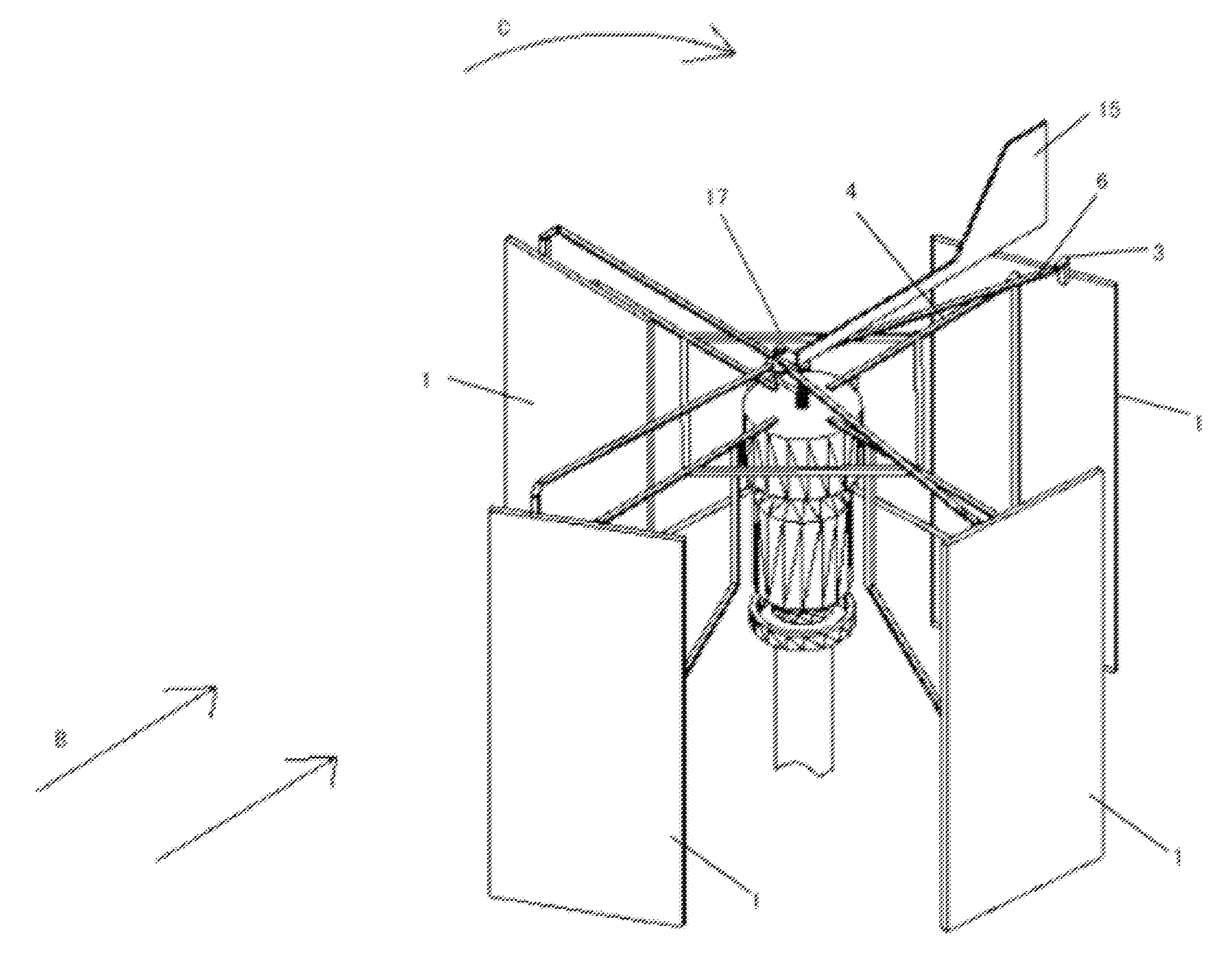
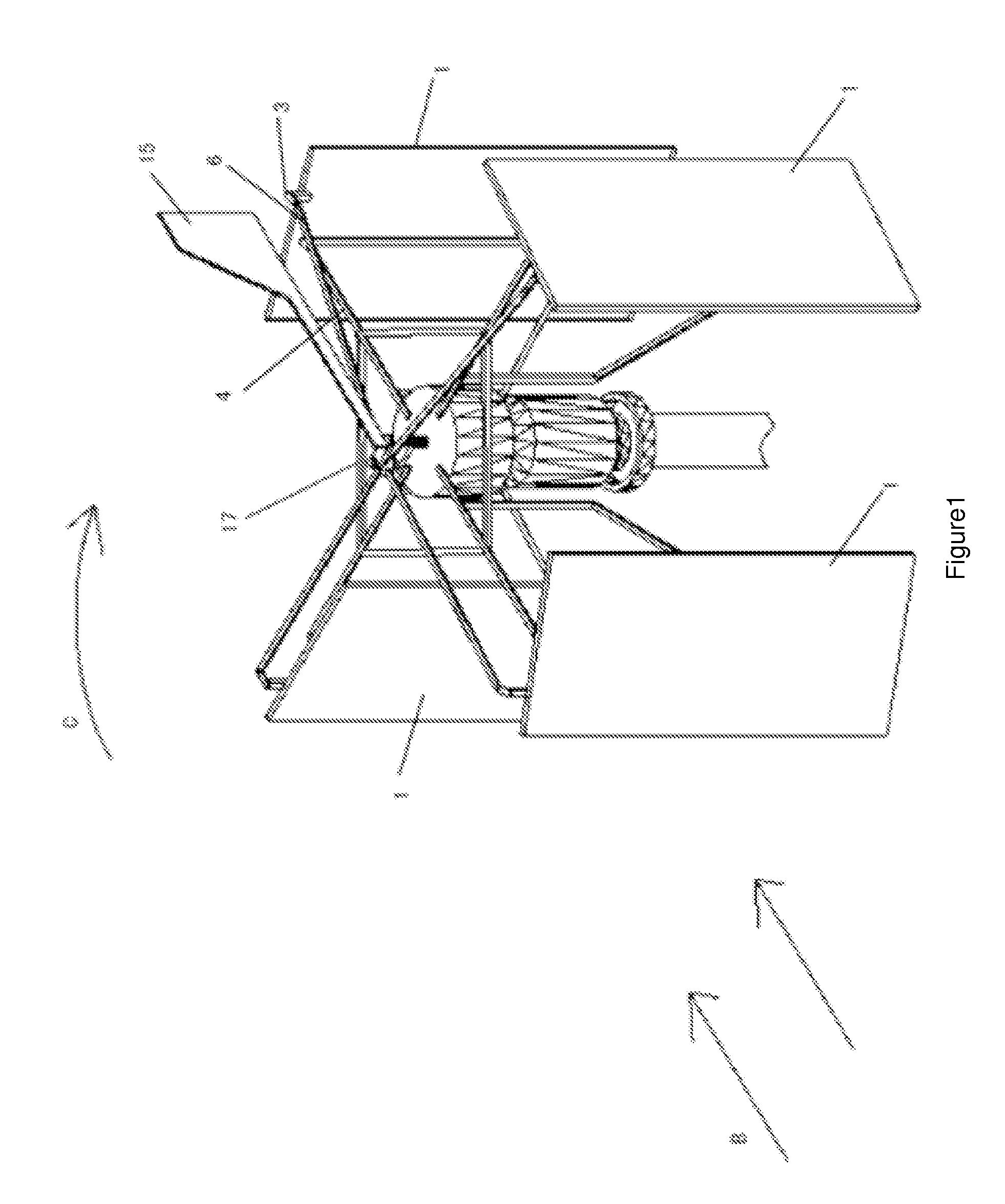
[0033]As shown in FIG. 1, FIG. 5 and FIG. 6, the present invention has disclosed a vertical shaft wind power system to adjust the windward of the fan blade automatically. It includes multiple fan blades 1, a rotary support 4, a fan blade support plate 5, a vertical generator input shaft 11, a transmission mechanism arranged between the fan blade support 5 and the input shaft 11. As shown in FIG. 5, an upper support 2a and a lower support 2b are arranged on the back of the fan blade 1, the outboard part of the rotary support 4 is pivotally connected with the upper support 2a and the lower support 2b (the upper and lower supports 2a, 2b are connected by pivot, they rotate around the pivot as the central axis), or they can be connected by hinge, or in other words they are rotating around an axis. The fan blade can rotate around the connection line between the upper and lower supports 2a, 2b and the rotary support 4, and the connection line is deemed as the axis. The internal side of th...

embodiment 2

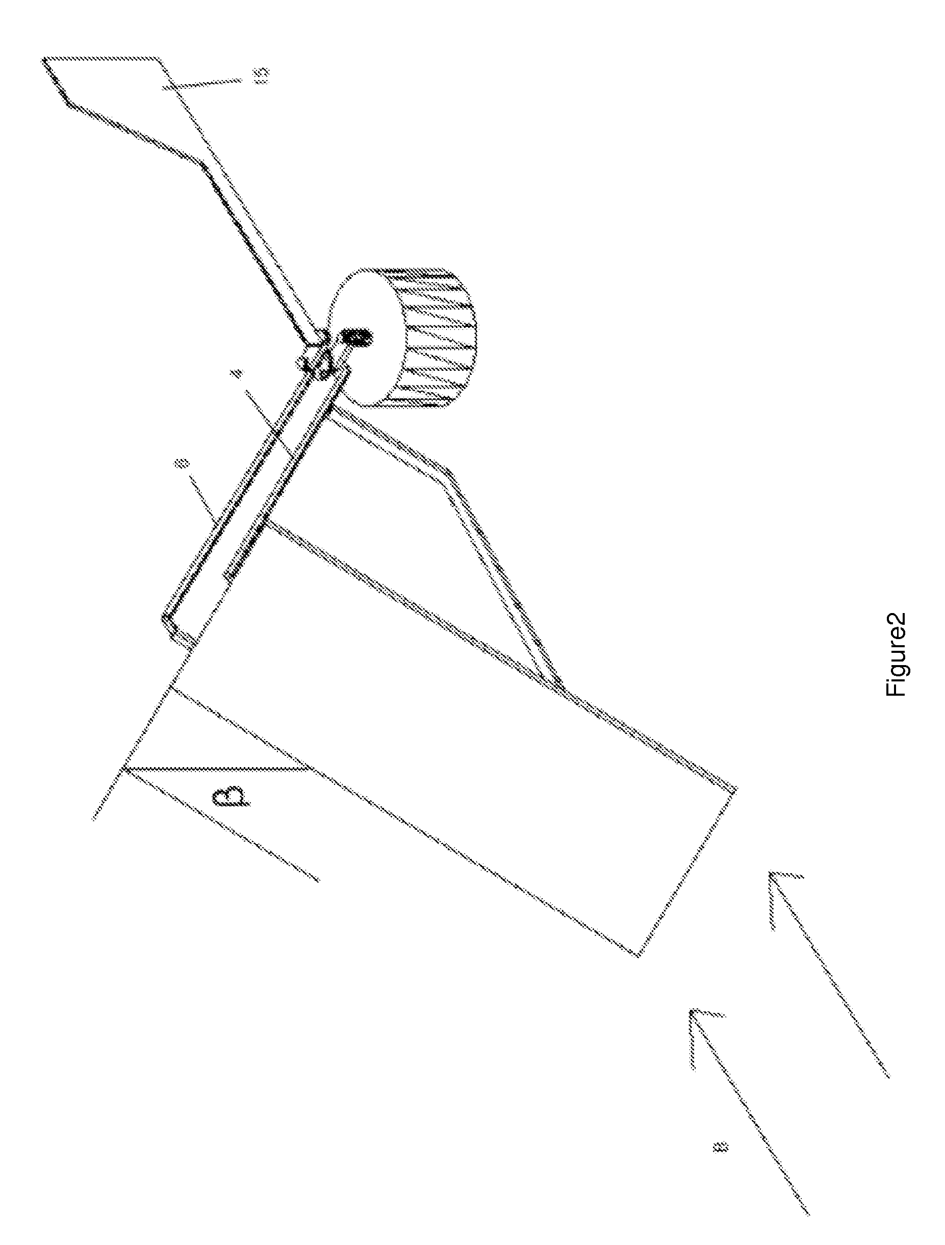
[0041]The mechanism to adjust the angle of the fan blade automatically in embodiment 1 has following disadvantages: when the windward side of the corner fan blade is following the wind, the fan blade draw bar arranged in the corner fan blade will have a small power onto the eccentric plate. At this time, the wind rudder will deviate from the wind direction, thus the fan blade direction can not meet with the wind direction best. The angle between the corner fan blade and the wind direction cannot be 0 degree when the corner fan blade is against the wind, therefore the wind power cannot be used sufficiently. On the other side, if the wind rudder is not expected to be deviate from the wind direction, the wind rudder must be made in very large size. This is not conducive to the development of the above-medium wind power device, and is also not conducive to the commercial development of products.

[0042]In embodiment 2, the mechanism to adjust the angle of the fan blade automatically is im...


PUM


Abstract

The present invention relates to a vertical shaft wind power system and an equipment to adjust the angle of the fan blade automatically, the system includes an equipment to adjust the fan blade automatically, in which the outboard side of the rotary support is pivotally connected with the back of the fan blade, the inner side of the rotary support is connected with the fan blade support plate, which is arranged in the vertical shaft wind power system and the rotary can roll together with the fan blade support plate; the power device is associated with the lower end of the positioning shaft to drive the positioning shaft to rotate; the rotary crankshaft is associated with the upper end of the positioning shaft, the rotary crankshaft can rotate with the positioning shaft synchronously; the eccentric shaft is arranged on the eccentric position of the rotary crankshaft, the eccentric shaft is sleeved with eccentric shaft, the eccentric shaft can rotate around the eccentric shaft; the outer end of the fan blade draw bar is rotatablely connected with the fan blade, the inner end of the fan blade is rotatablely connected with the eccentric plate; the mechanism consists of the rotary support, the fan blade draw bar and the fan blade can adjust the angle of the fan blade automatically, when the power device make the positioning shaft associated with the wind direction, the fan blade can rotate with wind to turn the windward side of the fan blade to the best position.

Description

FILED OF THE INVENTION[0001]The present invention relates to a vertical shaft wind power system and an equipment to adjust the angle of the fan blade automatically.BACKGROUND OF THE INVENTION[0002]The Chinese patent publication CN1858438 disclosed a kind of vertical shaft wind power system, which does not have a shaft in the pivot of the fan blade. The fan blade turning round the shaft forms a wind wheel. And the range of the rotational angle of the fan blade is controlled by the automatic control system. Hence, the blade will achieve the best blade rotational angle in different positions.[0003]However, no matter which way is adopted to change the rotational angle of the blade, there will still be the following defects:[0004]When the rotational blades are in the surface following the wind, the angle between the wind and the rotational blades can not be 90°. Thus the fan blades can not face the wind in the best position. And when the fan blades are in the surface against the wind, th...

Claims


Application Information

Patent Timeline
IPC IPC(8): F03D7/06F03D3/06
CPCF03D3/068F05B2260/76F05B2270/32F05B2270/321Y02E10/74
Inventor XU, ZHIWEN
Owner XU ZHIWEN
Why Eureka
Try Eureka