
Radio frequency circuit and signal transmission method

a radio frequency circuit and signal transmission technology, applied in the field of radio frequency circuits and signal transmission methods, can solve the problems of increased volume of mobile devices, failure of mobile device built-in antennas to provide such a large bandwidth, and increased difficulty in designing antennas

Active Publication Date: 2012-12-13
HTC CORP
View PDF11 Cites 5 Cited by
  • Summary
  • Abstract
  • Description
  • Claims
  • Application Information

AI Technical Summary

Benefits of technology

The patent describes a radio frequency circuit that uses a primary antenna and a secondary antenna to improve signal transmission. By using the primary antenna for specific signals and the secondary antenna for diversity reception, the circuit can provide better bandwidth and reduce the difficulty in designing the primary antenna. This results in a more efficient and compact antenna design for mobile devices.

Problems solved by technology

This results in an increased volume of the mobile device and also greater difficulty in designing the antennas.
Therefore, if the operating frequency band of the LTE communication system is to be covered within a reception range of the antenna, then the built-in antennae of the mobile device would fail to provide such a large bandwidth due to restrictions on the volume and use of the mobile device.

Method used


Image

  • Radio frequency circuit and signal transmission method
  • Radio frequency circuit and signal transmission method
  • Radio frequency circuit and signal transmission method

Examples


first embodiment

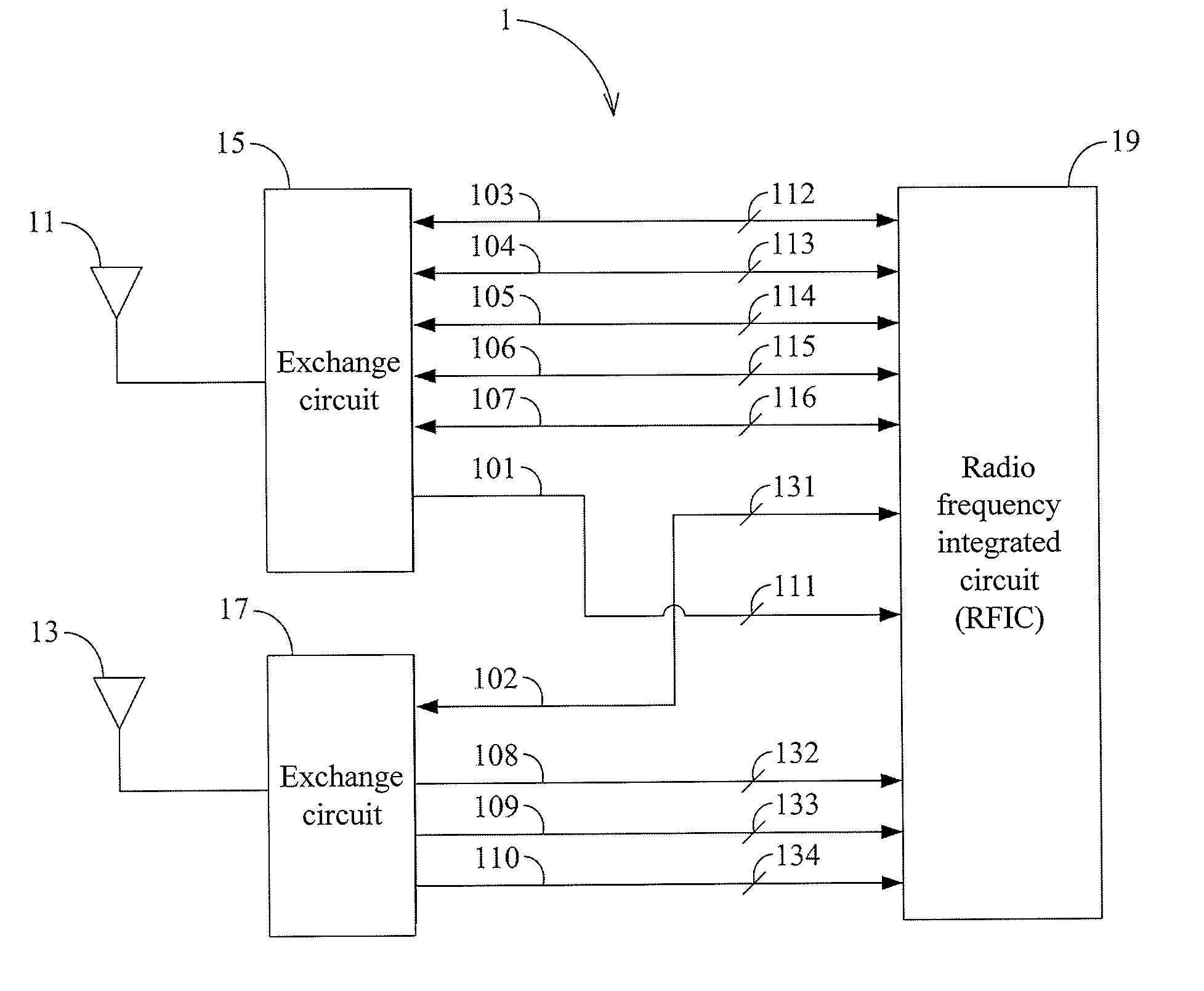
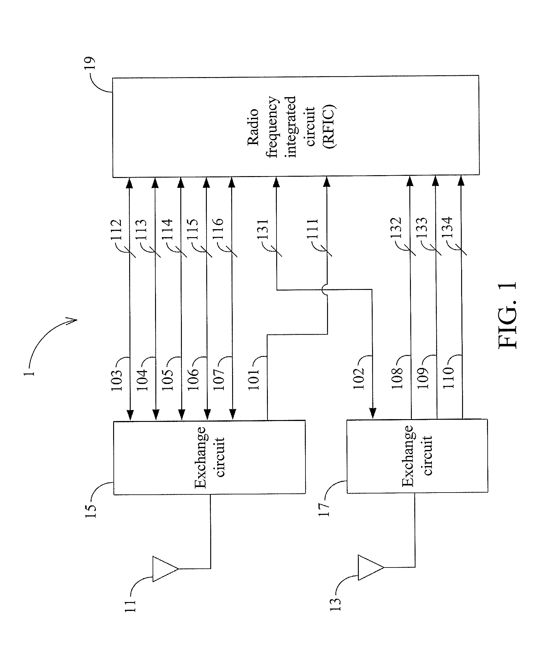
[0010]the present invention is a radio frequency circuit 1, a schematic view of which is depicted in FIG. 1. The radio frequency circuit 1 comprises a primary antenna 11, a secondary antenna 13, an exchange circuit 15, an exchange circuit 17, a radio frequency integrated circuit (RFIC) 19, a first transmission path 101, a second transmission path 102 and a plurality of transmission paths 103-110.

[0011]The primary antenna 11 is electrically coupled to the exchange circuit 15. The secondary antenna 13 is electrically coupled to the exchange circuit 17. The first transmission path 101 is electrically coupled to the exchange circuit 15 and the RFIC 19. The second transmission path 102 is electrically coupled to the exchange circuit 17 and the RFIC 19. The transmission paths 103-107 are electrically coupled to the exchange circuit 15 and the RFIC 19. The transmission paths 108-110 are electrically coupled to the exchange circuit 17 and the RFIC 19.

[0012]The primary antenna 11 is electric...

second embodiment

[0026]the present invention is a signal transmission method for a radio frequency circuit. The radio frequency circuit comprises an RFIC, a primary antenna and a secondary antenna. The primary antenna is electrically coupled to the RFIC, and is configured to transmit and receive at least one TRX signal. The secondary antenna is electrically coupled to the RFIC, and is configured to receive at least one DRX signal.

[0027]The signal transmission method of the second embodiment comprises the following steps. Firstly, step (a) is executed to enable the RFIC to receive a specific DRX signal via the primary antenna. Then, step (b) is executed to enable the RFIC to transmit and receive a specific TRX signal via the secondary antenna.

[0028]Furthermore, the radio frequency circuit may further comprise a first transmission path and a second transmission path. The first transmission path is electrically coupled to the primary antenna and the RFIC, and the second transmission path is electricall...


PUM


Abstract

A radio frequency circuit and a signal transmission method are provided. The radio frequency circuit comprises a primary antenna, a secondary antenna and a radio frequency integrated circuit. The primary antenna is electrically coupled to the radio frequency integrated circuit to transmit and receive at least one transmission / reception signal. The secondary antenna is electrically coupled to the radio frequency integrated circuit to receive at least one diversity reception signal. The radio frequency integrated circuit is configured to receive a specific diversity reception signal via the primary antenna and to transmit and receive a specific transmission / reception signal via the secondary antenna.

Description

FIELD OF THE INVENTION[0001]The subject application relates to a radio frequency (RF) circuit and a signal transmission method. More particularly, the subject application relates to a radio frequency circuit and a signal transmission method that allow for reducing the difficulty in designing an antenna.DESCRIPTIONS OF THE RELATED ART[0002]With development and advancement of wireless communication technologies, mobile phone systems have gradually evolved from the early Advanced Mobile Phone Systems (AMPSs) into the 2nd-generation (2G) mobile communication systems and further into the 3rd-generation (3G) mobile communication systems that are currently available as well as the 4th-generation (4G) mobile communication systems such as the Long Term Evolution (LTE) communication systems and Worldwide Interoperability for Microwave Access (WiMax) communication systems. In the evolution of the mobile phone systems, the radio spectrum that is used is increased continuously and, corresponding...

Claims


Application Information

Patent Timeline
Patent Type & Authority Applications(United States)
IPC IPC(8): H04W88/02
CPCH04B7/08H04B1/006
Inventor WU, WEI-YANGCHEN, WEI-CHIENMA, CHIEN-HUA
Owner HTC CORP
Learn More