
Image forming apparatus

a technology of forming apparatus and forming tube, which is applied in the direction of electrographic process apparatus, instruments, optics, etc., can solve the problems of color-shifted image production, low printing speed, color-shifted image production, etc., and achieve the effect of stable shape and size against the environment and less uneven properties

Inactive Publication Date: 2012-12-13
RICOH KK
View PDF3 Cites 16 Cited by
  • Summary
  • Abstract
  • Description
  • Claims
  • Application Information

AI Technical Summary

Benefits of technology

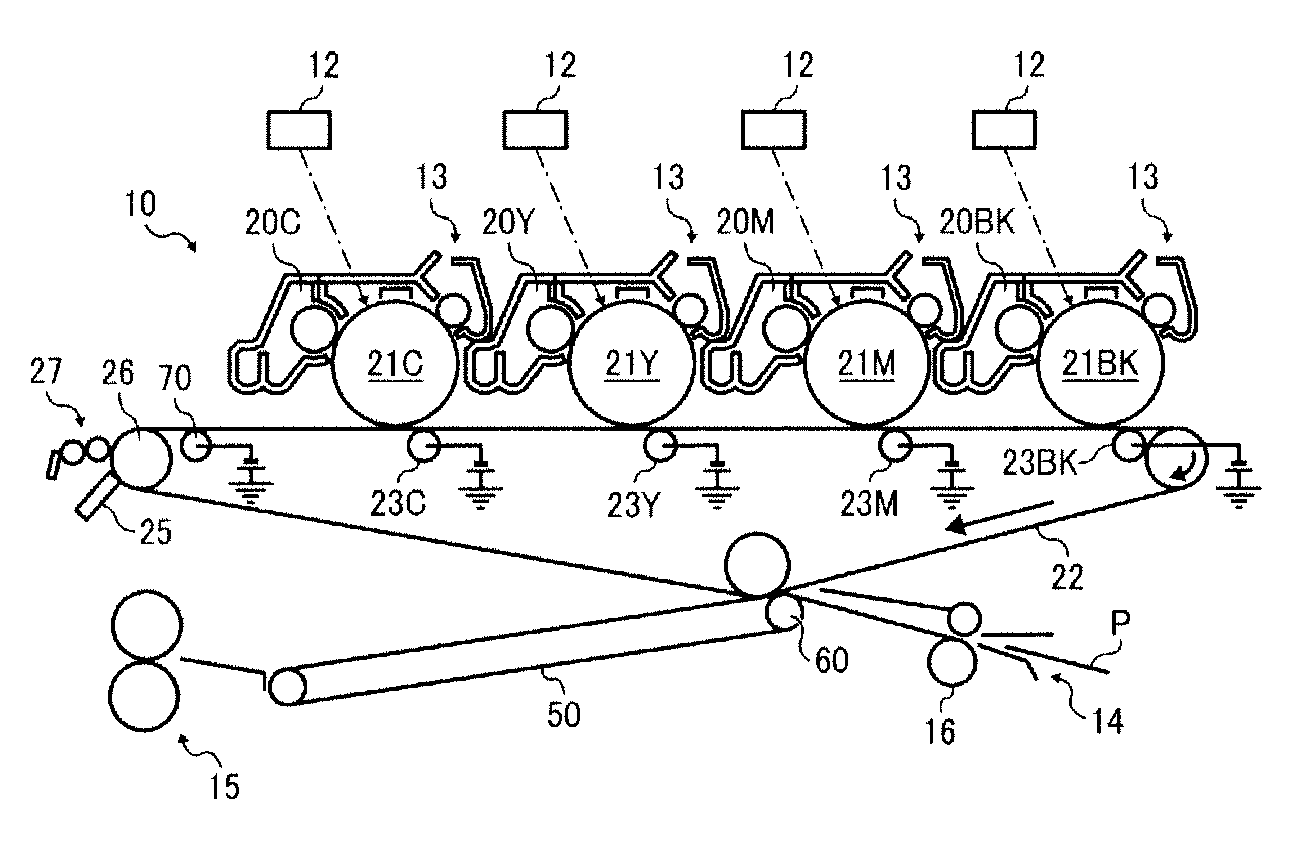
[0018]Accordingly, an object of the present invention to provide a large and high-speed intermediate transfer belt stably running for long periods, having less uneven properties and stable shape and size against the environment, and producing quality images without white spots.

Problems solved by technology

Four (color) image developers have been used for one photoreceptor when using the intermediate transfer belt, which had a disadvantage of low printing speed.
However, this is difficult to adjust positional preciseness of overlapping each color due to paper quality, etc., resulting in production of color-shifted images.
Such an enlarged intermediate transfer belt and a system using the belt have other problems the conventional belt / system do not have.
Specifically, the intermediate transfer belt slips on a drive roller driving the belt because of rotating at high speed, resulting in production of color-shifted images, or the belt is likely to be damaged when shifted.
Another problem is uneven properties of the belt.
One belt occasionally has uneven properties according to its positions, resulting in production of images having uneven quality.
A very large mold used to prepare a large belt having a circumferential length not less than 2,000 mm is difficult to uniformly control the temperature of the whole mold, and thought to have uneven properties.
A further problem is a white spot a toner is not transferred onto.
The apparatus having high linear speed needs to apply a high voltage to the belt travelling at high speed to pass a transfer nip in a shorter time, which is thought to cause white spots.
Another problem of the intermediate transfer belt is shape and size stability against environmental variation.
Then, the belt deteriorates in runnability, a toner image transferred onto the curled part is poorly transferred onto a paper, resulting in abnormal images such as stripe images.
However, the belt has a conventional size and possibly has insufficient runnability and other various troubles when enlarged.
Even such an apparatus has uneven temperature.
However, the backside roughness is not considered and stable runnability is difficult to obtain, and the white spot is not considered at all, either.
However, when used in a high-speed machine as a large belt, the belt possibly has problems of runnability and uneven properties because they are not considered.

Method used


Image

  • Image forming apparatus
  • Image forming apparatus
  • Image forming apparatus

Examples


example 1

[0118]A coating liquid was prepared to form a seamless belt.

[0119]First, as a substrate layer coating liquid, a polyimide varnish (U-varnish S from Ube Industries, Ltd.) including a polyimide resin precursor as a main component, which is a reactant between 3,3′,4,4′-biphenyltetracarboxylic dianhydride and p-phenylenediamine, and a polyimide varnish (U-varnish A from Ube Industries, Ltd.) including a polyimide resin precursor as a main component, which is a reactant between 3,3′,4,4′-biphenyltetracarboxylic dianhydride and 4,4′-diaminodiphenylether were mixed such that a polyamic acid solid content weight ratio (S / A) of the U-varnish S to the U-varnish A is 10 / 90 to prepare a mixture. A dispersion including N-methyl-2-pyrrolidone in which carbon black (Special Black 4 from Evonik-Degussa GmbH) was dispersed by a beads mill was mixed with the mixture such that the carbon black (CB) content was 16.5% by weight of the polyamic acid solid content to prepare a substrate layer coating liqu...

example 2

[0146]The procedure for preparation of the belt A in Example 1 was repeated to prepare a belt B having a circumferential length of 2,200 mm, a width of 376 mm except that the polyamic acid solid content weight ratios (S / A) of the U-varnish S to the U-varnish A in the substrate layer and the high-resistivity layer coating liquid were changed to 40 / 60, the CB content in the high-resistivity layer coating liquid was changed to 10.72% by weight, the amount of the high-resistivity layer coating liquid was changed to 1 / 3, and the mold A was changed to a mold B having the same size as that of the mold A and a blasted outer surface rougher than that thereof.

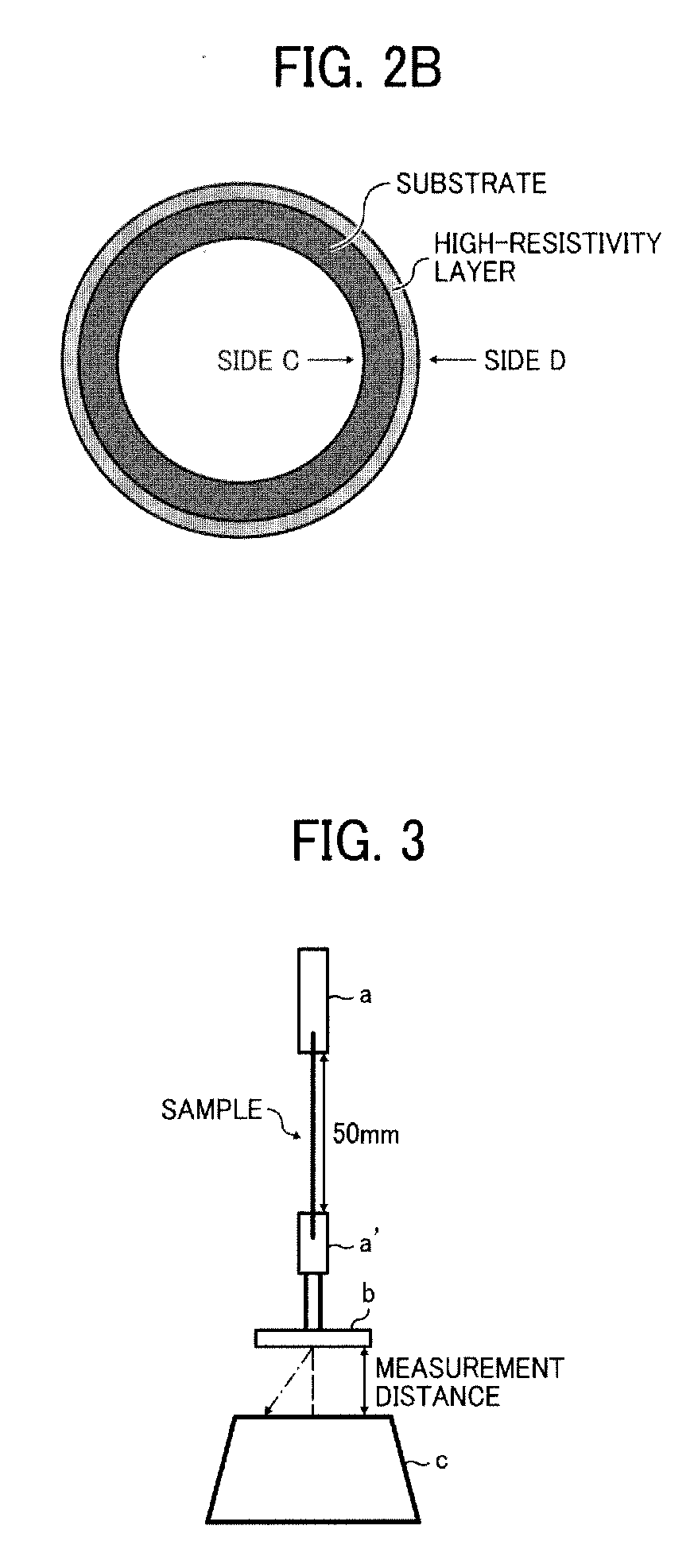
[0147]The belt had a thickness (t2) of 77 μm. The cross-section of the belt was observed by an SEM to find a high-resistivity layer was formed on the outer circumferential surface of the belt and had a thickness (t1) of 13 μm. The belt B had an inner circumferential surface having a roughness Ra of 0.39 μm.

[0148]The properties of the bel...

example 3

[0151]The procedure for preparation of the belt A in Example 1 was repeated to prepare a belt C having a circumferential length of 2,200 mm, a width of 376 mm except that the polyamic acid solid content weight ratios (S / A) of the U-varnish S to the U-varnish A in the substrate layer and the high-resistivity layer coating liquid were changed to 0 / 100, the CB content in the substrate layer was changed to 17.2% by weight, the CB content in the high-resistivity layer coating liquid was changed to 10.72% by weight, the amount of the high-resistivity layer coating liquid was changed to 2 / 3, and the mold A was changed to a mold B having the same size as that of the mold A and a blasted outer surface rougher than that thereof.

[0152]The belt had a thickness (t2) of 83.9 μm. The cross-section of the belt was observed by an SEM to find a high-resistivity layer was formed on the outer circumferential surface of the belt and had a thickness (t1) of 20.5 μm. The belt C had an inner circumferentia...


PUM


Abstract

An intermediate transfer belt having a circumferential length not less than 2,000 mm and is driven at a linear speed not less than 350 mm / sec and an inner circumferential surface having a surface roughness Ra of from 0.2 to 0.4 nm (JIS B0601: '01), and including a substrate layer and a high-resistivity layer having a resistivity higher than that of the substrate layer, wherein the high-resistivity layer has a surface resistivity higher than that of the substrate layer by 0.3 to 2.5 log Ω / □ in common logarithm value when applied with a voltage of 500 V.

Description

CROSS-REFERENCE TO RELATED APPLICATIONS[0001]This patent application is based on and claims priority pursuant to 35 U.S.C. §119 to Japanese Patent Applications Nos. 2011-126943 and 2012-102106, filed on Jun. 7, 2011 and Apr. 27, 2012, respectively in the Japanese Patent Office, the entire disclosure of which is hereby incorporated herein by reference.FIELD OF THE INVENTION[0002]The present invention relates to an image forming apparatus using a seamless belt such as copiers and printers, and particularly to an image forming apparatus using an intermediate transfer belt preferably used for forming full-color images.BACKGROUND OF THE INVENTION[0003]Conventionally, seamless belts are used in various applications in electrophotographic image forming apparatus. Particularly, in recent full-color electrophotographic image forming apparatus, an intermediate transfer belt is used, on which four developed yellow, magenta, cyan and black images are overlapped and the overlapped images are tra...

Claims


Application Information

Patent Timeline
IPC IPC(8): G03G15/01
CPCG03G15/162
Inventor TAKAHASHI, HIROAKI
Owner RICOH KK
Learn More