
Wide-Bandwidth Linear Regulator

Inactive Publication Date: 2012-12-13
IBM CORP
View PDF4 Cites 11 Cited by
  • Summary
  • Abstract
  • Description
  • Claims
  • Application Information

AI Technical Summary

Benefits of technology

[0007]A linear regulator and a method of regulating a supply voltage are provided. Embodiments include a linear regulator with a first feedback loop and a second feedback loop. The first feedback loop is characterized by a first bandwidth and a first gain. The first feedback loop includes a first amplifier characterized by an output impedance which is significantly reduced in order to maximize the bandwidth of the first feedback loop when driving the capacitance of a control input of a series pass element. The second feedba

Problems solved by technology

Maintaining accurate voltage regulation is particularly challenging when the load current variations are sudden and extreme, e.g. minimum load to maximum load demand in a short period of time.
Hence, any linear regulator requires a finite amount of time to correct the output voltage after a change in load current demand.
However, the need to maintain adequate loop stability (phase margin) limits the achievable bandwidth of most linear regulators.
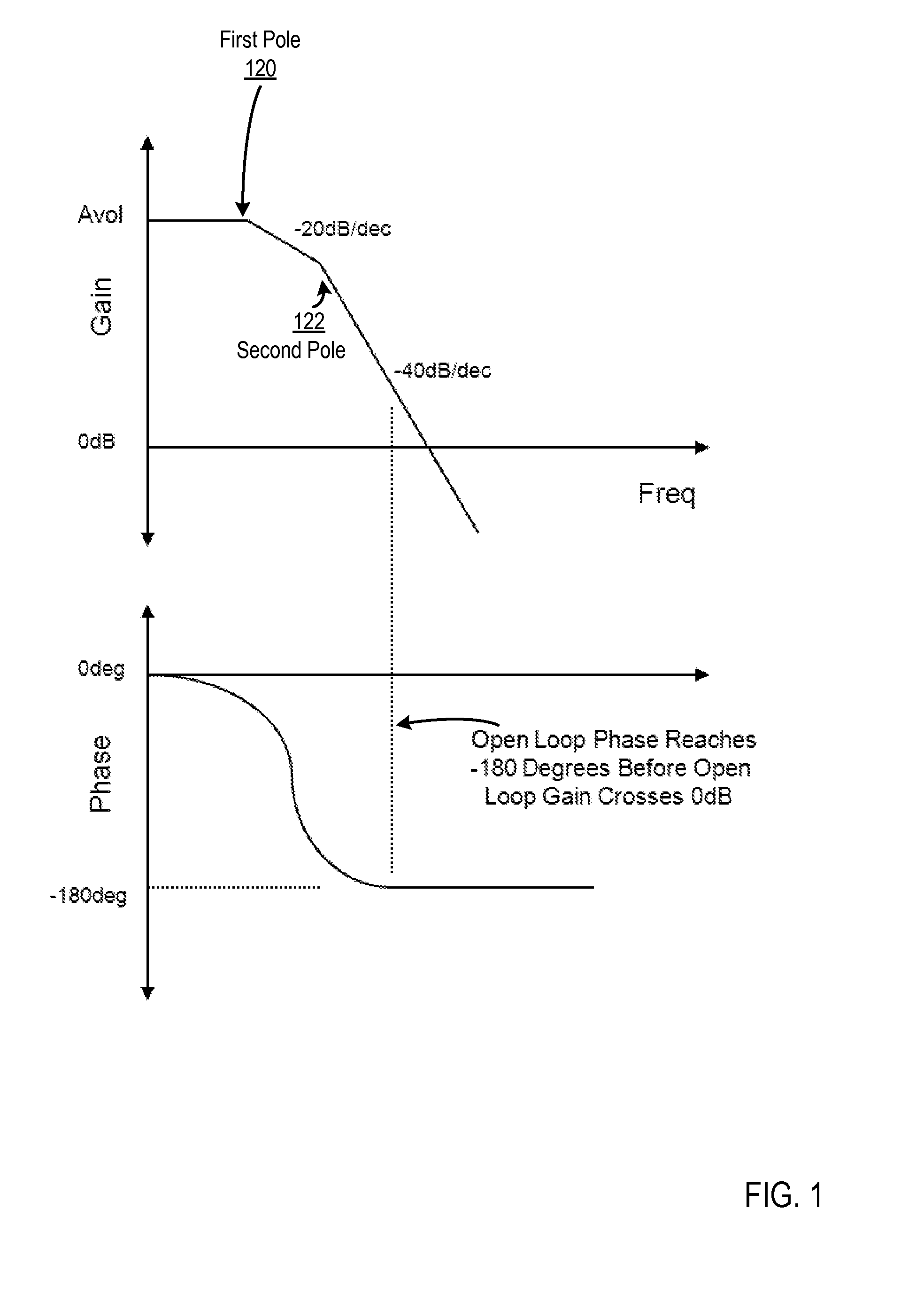
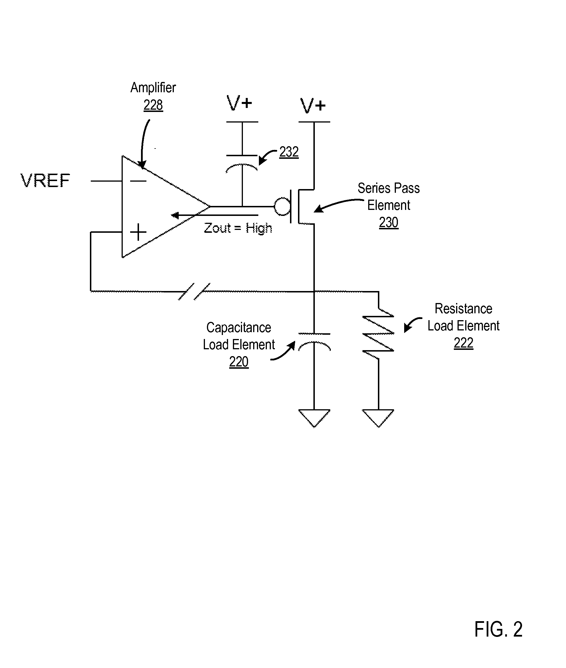
Filtering of regulated voltage domains with decoupling networks and parasitic device capacitances form time constants called ‘poles’ which cause accumulated phase shift in the regulator's open loop response.
Such accumulated phase shift in the open loop can cause ringing or even oscillation at the linear regulator's output as the net phase approaches 180 degrees.
Otherwise, the feedback error signal will become regenerative and cause instability in the loop.
Furthermore, as illustrated in FIG. 1, if the open loop gain has not been attenuated to less than unity prior to the open loop phase accumulation reaching 180 degrees, loop oscillation will result.

Method used


Image

  • Wide-Bandwidth Linear Regulator
  • Wide-Bandwidth Linear Regulator
  • Wide-Bandwidth Linear Regulator

Examples


Embodiment Construction

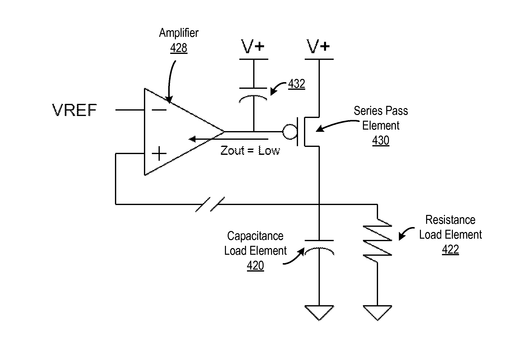
[0017]Examples of linear regulators and methods of regulating a power supply in accordance with the present invention are described with reference to the accompanying drawings, beginning with FIG. 3. FIG. 3 sets forth a bode diagram illustrating frequency and phase response of an example linear regulator illustrated in FIG. 4, according to embodiments of the present invention. The example linear regulator of FIG. 4 includes a series pass element (430), a capacitance load element (420), a resistance load element (422), and an amplifier (428) with an input gate impedance (432). As in FIGS. 1-2, a first pole (320) is formed due primarily to the impedance of the load of the regulator of FIG. 4, specifically the load capacitance element (420) and load resistance element (422). The second pole (322) is formed due to the output impedance (426) of the amplifier (428) and the input gate capacitance (432) of the series pass element (430). In order to maintain the unconditional stability of th...


PUM


Abstract

A linear regulator and a method of regulating a supply voltage are provided. Embodiments include a linear regulator with a first feedback loop and a second feedback loop. The first feedback loop is characterized by a first bandwidth and a first gain. The first feedback loop includes a first amplifier characterized by an output impedance which is significantly reduced in order to maximize the bandwidth of the first feedback loop when driving the capacitance of a control input of a series pass element. The second feedback loop is characterized by a second bandwidth and a second gain. The second feedback loop includes a second amplifier that controls the current in the first amplifier in the first feedback loop.

Description

BACKGROUND OF THE INVENTION[0001]1. Field of the Invention[0002]The field of the invention is data processing, or, more specifically, a wide-bandwidth linear regulator and a method of regulating a power supply.[0003]2. Description of Related Art[0004]A voltage regulator is an electrical circuit designed to maintain a constant voltage level at its output even as operating conditions change over time. Every electronic circuit is designed to operate off of some supply voltage, which is usually desired to be constant. A voltage regulator provides this constant DC output voltage and contains circuitry that continuously holds the output voltage at the desired value regardless of changes in load current or input voltage (this assumes that the load current and input voltage are within the specified operating range for the regulator). We address the issue of voltage regulation, specifically, on-chip regulation of potentially noisy external power supplies to create a high DC accuracy, low AC ...

Claims


Application Information

Patent Timeline
IPC IPC(8): G05F1/575
CPCG05F1/575G05F1/56
Inventor HUNTER, BRADFORD L.RASMUS, TODD M.
Owner IBM CORP
Learn More