
Drive device

a technology of drive device and drive shaft, which is applied in the direction of piezoelectric/electrostrictive/magnetostrictive devices, piezoelectric/electrostriction/magnetostriction machines, electrical apparatus, etc., can solve the problems of low speed performance and poor efficiency of ultrasonic linear actuator, poor efficiency, and inability to drive the above ultrasonic linear actuator. achieve the effect of improving energy efficiency, increasing displacement vibration, and improving movement speed

Inactive Publication Date: 2012-11-29
KONICA MINOLTA INC +1
View PDF9 Cites 5 Cited by
  • Summary
  • Abstract
  • Description
  • Claims
  • Application Information

AI Technical Summary

Benefits of technology

[0015]The present invention has been made in view of the above circumstances, and an object thereof is to provide a drive device capable of increasing displacement vibration to improve a movement speed, and improve energy efficiency.
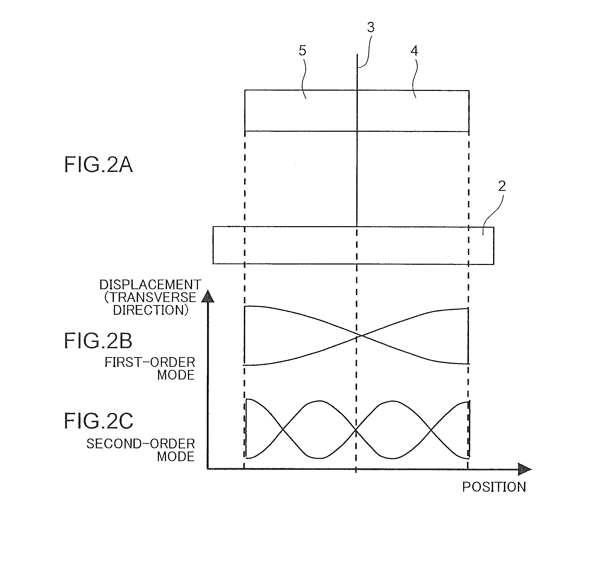
[0016]A drive device of the present invention is adapted to move a driven member based on a speed difference between during extending and during contracting in a course of vibration of a vibrator. The vibrator is formed in a structure which has two resonance modes identical in terms of a vibration direction, and allows a ratio between respective resonance frequencies of the two resonance modes to become approximately 2. A drive signal to be given to the vibrator is configured to approximately conform to the two resonance modes. The drive device having the above configuration makes it possible to generate pseudo-sawtooth displacement vibration multiplied by an amplitude amplification factor Q through resonance, thereby improving a movement speed, and allow a larger part of input energy to be used for mechanical vibration, thereby improving energy efficiency.

Problems solved by technology

However, the above ultrasonic linear actuator has problems of low speed performance and poor efficiency as compared to other types of ultrasonic motors similarly using a piezoelectric element, such as standing wave-type and traveling wave-type ultrasonic motors.
Further, in the case of utilizing resonance, input energy is mostly used for mechanical vibration, whereas, in the case of utilizing no resonance, the energy is used for charge and discharge of an electrical capacitor made with a dielectric and constituting the piezoelectric element, which leads to poor efficiency.
This means that it is impossible to drive the above ultrasonic linear actuator.

Method used


Image

  • Drive device
  • Drive device
  • Drive device

Examples


first embodiment

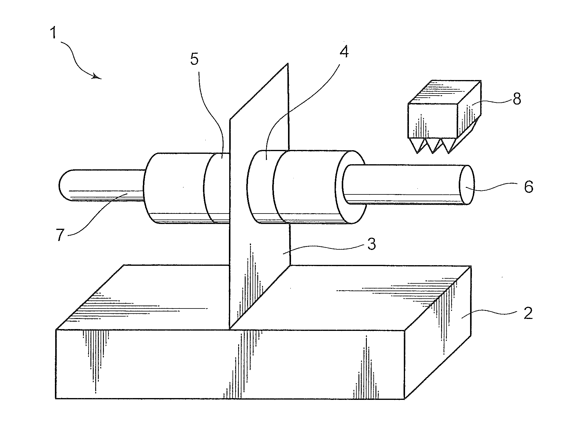
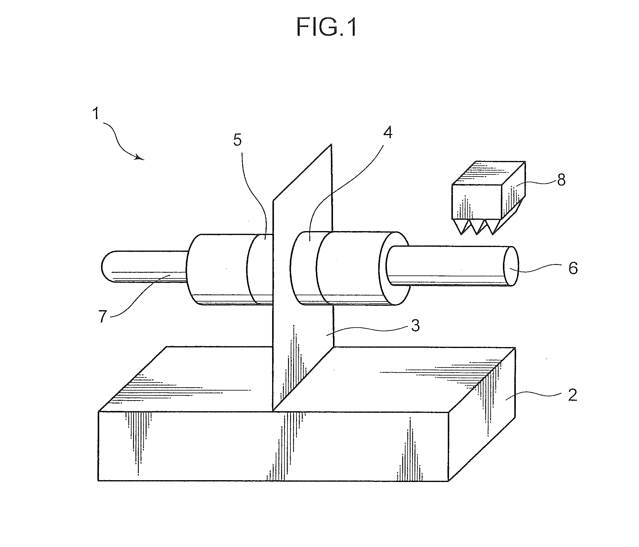
[0045]FIG. 1 is a perspective view schematically illustrating a structure of an ultrasonic linear actuator 1 which is a drive device according to a first embodiment. This ultrasonic linear actuator 1 comprises a fixed member 2, a support plate 3, a piezoelectric element 4, a piezoelectric element 5, a driving member 6, a driving member 7, and a driven member 8. The ultrasonic linear actuator 1 is roughly configured such that the piezoelectric elements 4, 5 each serving as a first vibrator are attached, respectively, to opposite surfaces of the support plate 3 provided to stand upwardly from the fixed member 2, wherein the driving members 6, 7 are attached, respectively, to distal edge faces of the piezoelectric elements 4, 5, and the driven member 8 is provided with respect to at least one of the driving members 6, 7 (in FIG. 1, only the driving member 6) in a frictionally engageable manner.

[0046]The support plate 3 is capable of supporting a weight of the piezoelectric elements 4, ...

second embodiment

[0068]FIG. 9(A) is a side view schematically illustrating a structure of an ultrasonic linear actuator which is a drive device according to a second embodiment. In this ultrasonic linear actuator 11, an element or component similar to and corresponding to that in the ultrasonic linear actuator 1 illustrated in FIGS. 1 and 4 is assigned with the same reference numeral or code, and its description will be omitted. In the ultrasonic linear actuator 11, at least in the predetermined range W, an outer peripheral surface of a rod-shaped driving member 16 is formed as a continuous curved surface, i.e., the diameter of the driving member 16 is smoothly (continuously) changed in an axial direction thereof.

[0069]In FIG. 9(A), the outer peripheral surface of the driving member 16 is formed as a continuous curved surface over approximately the entire length thereof. Further, a driving member 17 having a constant diameter is coupled to a distal end of the driving member 16, and a driven member 8...

third embodiment

[0074]FIGS. 10 and 11 are side views schematically illustrating respective structures of two types of ultrasonic motors each of which is a drive device according to a third embodiment. In these ultrasonic motors 1a, 11a, an element or component similar to and corresponding to that in the ultrasonic linear actuators 1, 11 illustrated in FIGS. 1, 4 and 9 is assigned with the same reference numeral or code, and its description will be omitted. In the ultrasonic motors 1a, 11a, a driven member 28 comprises a rotor 28a having an outer peripheral surface serving as an engagement section with respect to a driving member 6, 16, and an output take-out shaft 28b serving as a rotary shaft of the rotor. The an output take-out shaft 28b is rotatably supported by a pair of brackets 28c, and the bracket 28c is elastically biased by a support member 28b in a direction from a fixed position of a fixed member 2 or the like toward the driving member 6, 16.

[0075]Based on this configuration, a displacem...


PUM


Abstract

Disclosed is a drive device 1 which is adapted to move a driven member used on a speed difference between during extending and during contracting in a course of vibration of a vibrator. The vibrator, e.g., a piezoelectric element 4, 5, is formed in a structure which has two resonance modes identical in terms of a vibration direction, and allows a ratio between resonance frequencies of the two resonance modes to become approximately 2. A drive signal to be given to the vibrator is configured to approximately conform to the two resonance modes. The drive device 1 having the above configuration makes it possible to generate pseudo-sawtooth displacement vibration multiplied by an amplitude amplification factor Q through resonance, thereby improving a movement speed, and allow a larger part of input energy to be used for mechanical vibration, thereby improving energy efficiency.

Description

CROSS REFERENCE TO RELATED APPLICATIONS[0001]This is a U.S. national stage of application No. PCT / JP2011 / 000560, filed on 2 Feb. 2011. Priority under 35 U.S.C. §119(a) and 35 U.S.C. §365(b) is claimed from Japanese Application No. 2010-023394, filed 4 Feb. 2010, the disclosure of which are also incorporated herein by reference.TECHNICAL FIELD[0002]The present invention relates to a drive device suitably implementable as an ultrasonic linear actuator using the SIDM (Smooth Impact Drive Mechanism (registered trademark)).BACKGROUND ART[0003]For example, an ultrasonic linear actuator has a structure schematically illustrated in FIG. 20, wherein it is adapted to transmit extending and contracting of a piezoelectric element to a rod (driving shaft), and move a driven member (movable body) engaged with the rod with a predetermined frictional force, based on a speed difference between during extending and during contracting of the piezoelectric element. For example, when the rod is extended...

Claims


Application Information

Patent Timeline
Patent Type & Authority Applications(United States)
IPC IPC(8): H02N2/00
CPCH02N2/025H02N2/067H02N2/101
Inventor MORITA, TAKESHIYOSHIDA, RYUICHI
Owner KONICA MINOLTA INC
Learn More