
Rolling bearing for inverter-driven motor and inverter-driven motor therewith

a technology of inverter-driven motors and rolling bearings, which is applied in the direction of magnetic circuit rotating parts, magnetic circuit shape/form/construction, mechanical apparatus, etc., can solve the problems of low local melting of material inside the bearing, and the development of poor lubrication or abnormal noise, etc., to achieve smooth and continuous rotation, reduce the effect of mechanical loss and long service li

Inactive Publication Date: 2012-11-15
MINEBEA CO LTD +1
View PDF0 Cites 14 Cited by
  • Summary
  • Abstract
  • Description
  • Claims
  • Application Information

AI Technical Summary

Benefits of technology

[0010]The present invention was completed by considering the above problems, and objects thereof are to provide a rolling bearing for an inverter-driven motor in which the oil film thickness in a steady operation condition is stably maintained in a specific range, the withstand voltage can be controlled, and whereby, the discharge due to the shaft voltage of the inverter-driven motor is prevented and electrolytic corrosion can be suppressed.
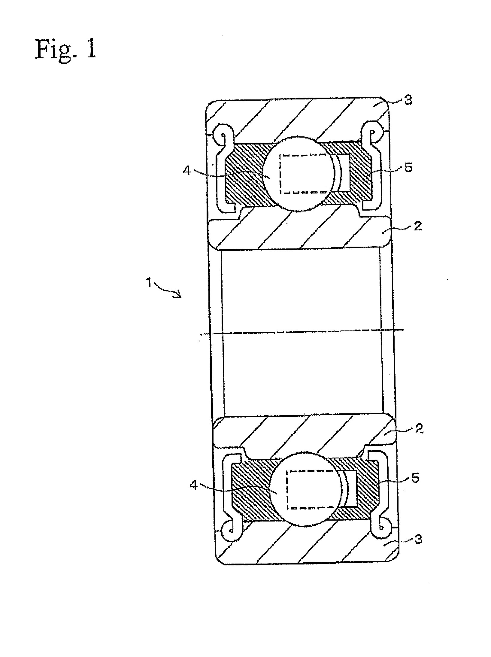
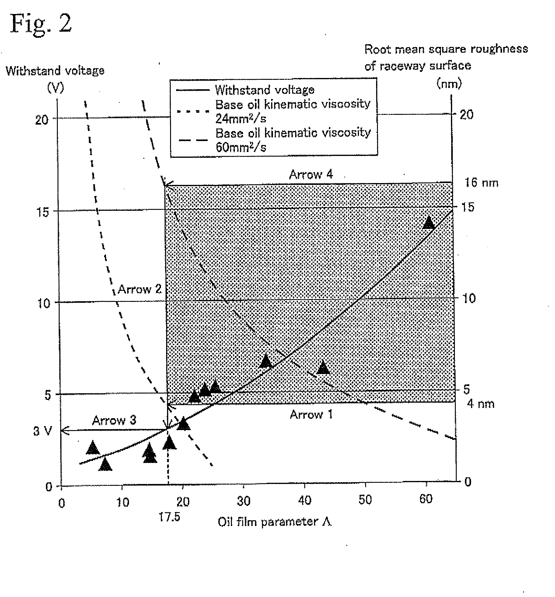
[0013]According to the rolling bearing for the inverter-driven motor of the present invention, by setting the root mean square roughness of the raceway surface where the rolling elements roll to be in the range of 4 to 16 nm, and by setting the oil film parameter Λ in a steady operation condition to be at least 17.5, the formation condition of the oil film can be suitably controlled, and thereby discharge at a voltage lower than a specific voltage can be prevented and electrolytic corrosion can be prevented.
[0017]Furthermore, in the rolling bearing for the inverter-driven motor of the present invention, since the electrolytic corrosion is suppressed by controlling the range of base oil kinematic viscosity of grease, mechanical loss does not increase, and long service life is also achieved. Therefore, an inverter-driven motor in which a bearing can be smoothly and continuously rotated for long period can also be easily provided at low cost.
[0018]According to the rolling bearing for the inverter-driven motor of the present invention, the oil film thickness in a steady operation condition is stably maintained in a specific range, the withstand voltage can be controlled, and thereby, the discharge due to the shaft voltage of the inverter-driven motor is prevented and electrolytic corrosion can be suppressed.

Problems solved by technology

As a result, local melting of material inside the bearing, so-called electrolytic corrosion, is generated.
In the case in which this electrolytic corrosion progresses, a corrugation phenomenon occurs at the surface of the bearing inner ring, the bearing outer ring and the rolling element, so that poor lubrication or abnormal noises occur, and this is one of the primary factors of the problems in the motor.
However, in this technique of increasing the withstand voltage by strengthening the insulation, although the electrolytic corrosion is avoided thanks to the perfect insulation obtained by the use of rolling elements made by silicon nitride, a bearing using the rolling elements made of silicon nitride becomes very expensive, and producing a motor with such bearing involves a problem of cost.
However, in the technique which provides the discharge brush, there is a problem in that, when conductivity of discharge brush is decreased by abrasion, electric resistance of the discharge brush increases becoming higher than that between the inner and outer rings and the rolling element, and electric conduction between the inner and outer rings is resumed.
Another problem is that abrasion powder produced from the discharge brush may cause damage at inside of the bearing.
However, there is a problem in that although the discharges are small, roughness of the contact surface is increased and ultimately, service life of the bearing is shortened.

Method used


Image

  • Rolling bearing for inverter-driven motor and inverter-driven motor therewith
  • Rolling bearing for inverter-driven motor and inverter-driven motor therewith
  • Rolling bearing for inverter-driven motor and inverter-driven motor therewith

Examples


example 1

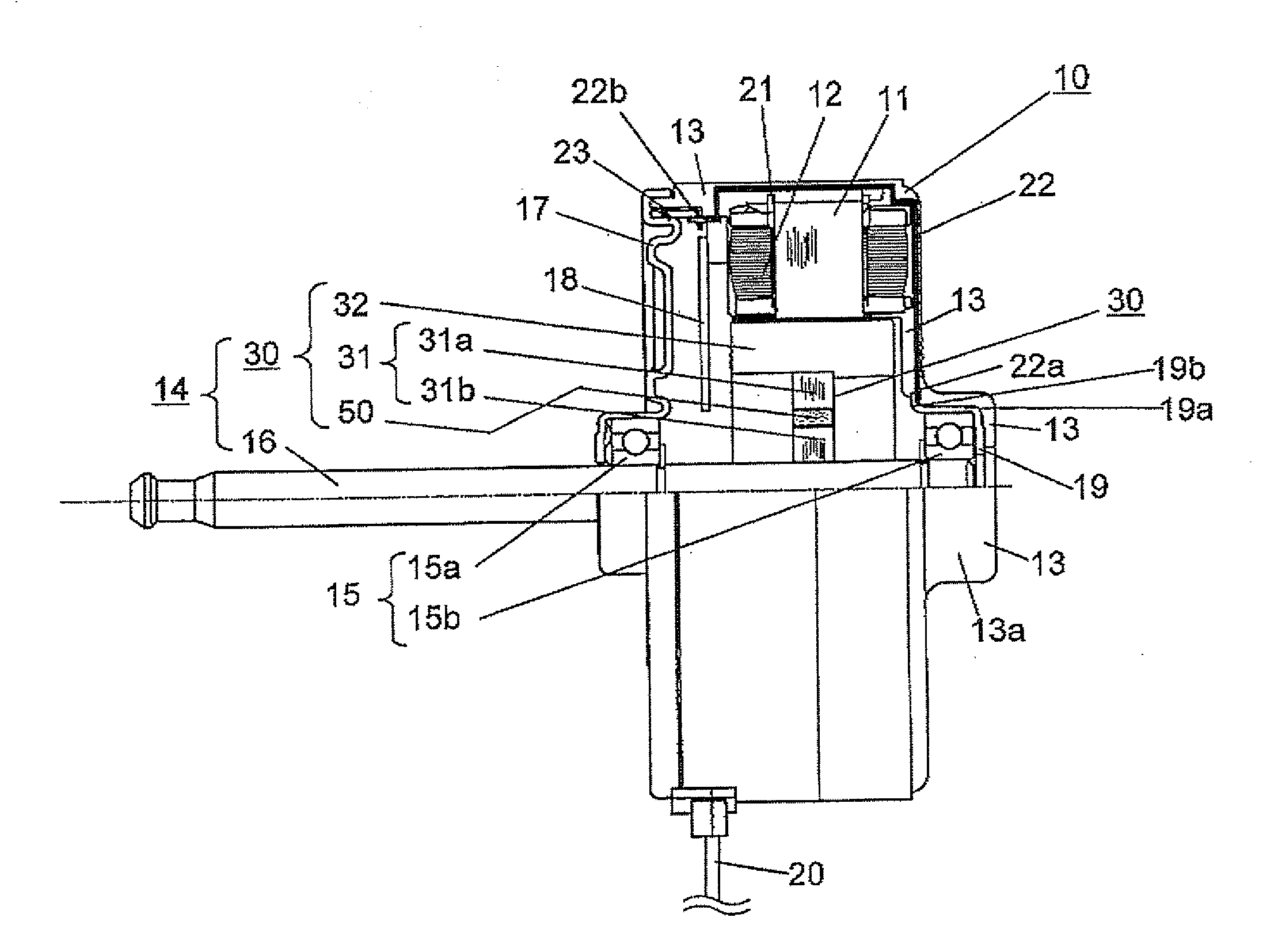
[0077]As shown in Table 1, grease having a kinematic viscosity at 40° C. of 55 nm2 / s and comprising ester oil as a base oil and lithium soap as a thickener, was used. This grease was supplied at a required amount in a ball bearing (trade name: 608ZZ, produced by Minebea Co., Ltd., outer diameter: 22 mm, inner diameter: 8 mm, width: 7 mm) in which the root mean square roughness on the raceway surface of the inner ring was 8 nm. By this way, a rolling bearing for an inverter-driven motor of Example 1 according to the present invention having an oil film parameter Λ of 26 at 1000 rpm was produced.

TABLE 140° C. baseRacewayoilWithstandVoltagesurfacekinematicvoltage ofmaximumOil filmroughnessviscositybearingTestvalue (V)parameter Λ(nm)(mm2 / s)(V)EvaluationExample 13268555.3NoelectrolyticcorrosionComparative101614552.3ElectrolyticExample 1corrosionComparative3148261.9ElectrolyticExample 2corrosion


PUM


Abstract

A rolling bearing for an inverter-driven motor has the thickness of an oil film in a steady operation condition stably maintained in a specific range, by which the withstand voltage can be controlled, and the discharge due to the shaft voltage of the inverter-driven motor is prevented and electrolytic corrosion can be suppressed. The rolling bearing for an inverter-driven motor has an inner ring, an outer ring, a rolling element, and grease, wherein a root mean square roughness of a raceway surface of at least one of the inner ring and the outer ring is 4 to 16 nm, and an oil film parameter Λ in steady operation is at least 17.5.

Description

BACKGROUND OF THE INVENTION[0001]1. Field of the Invention[0002]The present invention relates to a rolling bearing for inverter-driven motors, such as an air conditioner motor, which suppresses generation of electrolytic corrosion, and relates to an inverter-driven motor using the rolling bearing.[0003]2. Description of Related Art[0004]Recently, motors using pulse width modulation (hereinafter, referred to as a PWM), in which the motor is driven by an inverter, have increased. In such a PWM inverter driving method, since a neutral point potential of winding does not become zero, a potential difference (hereinafter, referred to as a shaft voltage) is often, generated between an outer ring and an inner ring of the rolling bearing which supports the shaft. This shaft voltage contains a high frequency component caused by switching, and when the shalt voltage reaches the dielectric breakdown voltage of the oil film in the bearing, small current flows at the inside of the bearing, and el...

Claims


Application Information

Patent Timeline
Patent Type & Authority Applications(United States)
IPC IPC(8): H02K7/08F16C19/02F16C33/58F16C19/00
CPCH02K1/30H02K5/1732F16C41/008F16C33/6633F16C2380/26H02K11/0089H02K11/40F16C2240/54F16C19/52
Inventor KOMIYAMA, HIROSHIMACHIDA, SHINICHIMAETANI, TATSUOISOMURA, YOSHINORI
Owner MINEBEA CO LTD
Learn More