
Air disinfection and cleaning device, and exhaled gas disinfection and cleaning device, interior air disinfection and cleaning device, and simplified isolation device using the same

a technology of exhaled gas and disinfection device, which is applied in the direction of lighting and heating apparatus, instruments, heating types, etc., can solve the problems of not being able to achieve the above disinfection of exhaled gas, and being unable to perfect prevent airborne infection, etc., to achieve the effect of effective disinfection of air, high disinfection effect, and small volum

Inactive Publication Date: 2012-11-15
TKB
View PDF1 Cites 56 Cited by
  • Summary
  • Abstract
  • Description
  • Claims
  • Application Information

AI Technical Summary

Benefits of technology

"The present invention aims to provide a small and efficient air disinfection and cleaning device that can be used in various settings. The device can effectively disinfect and clean the air, while being easy to install and operate. Additionally, the invention includes an exhaled gas disinfection and cleaning device, an interior air disinfection and cleaning device, and a simplified isolation device that utilizes the same technology."

Problems solved by technology

However, a mask is capable of preventing bacteria from invading into the respiratory organs at the time of wearing, while as long as there are bacteria in an interior air, it is impossible to perfectly prevent airborne infection.
However, conventional mechanical ventilators have exhausted an exhaled gas breathed out by a patient into a room without disinfection, so that there used to be a risk of airborne infection of the bacteria contained in an exhaled gas of a patient to medical workers and other patients.
However, in Patent Document 1 described above, there is a description to disinfect an exhaled gas of a patient with an ultraviolet disinfection lamp, while there is no description at all of a specific configuration to carry out it, and thus it used not to be possible to achieve the above disinfection of an exhaled gas based on the description in Patent Document 1.
Since the deodorizing device in Patent Document 2 described above has a configuration of attaching the spiral fin 2 on an outer periphery of the electric lamp 1 generating ultraviolet rays, there used to be a problem that the fin 2 blocks ultraviolet rays to decrease an amount of ultraviolet radiation to the gas and thus effective disinfection cannot be carried out.
However, in this case, the deodorizing device gets larger as a whole, which is no longer a size to fit into an exhalation circuit of a mechanical ventilator and becomes an excessively large scale device for disinfection of an exhaled gas for one patient.

Method used


Image

  • Air disinfection and cleaning device, and exhaled gas disinfection and cleaning device, interior air disinfection and cleaning device, and simplified isolation device using the same
  • Air disinfection and cleaning device, and exhaled gas disinfection and cleaning device, interior air disinfection and cleaning device, and simplified isolation device using the same
  • Air disinfection and cleaning device, and exhaled gas disinfection and cleaning device, interior air disinfection and cleaning device, and simplified isolation device using the same

Examples


first embodiment

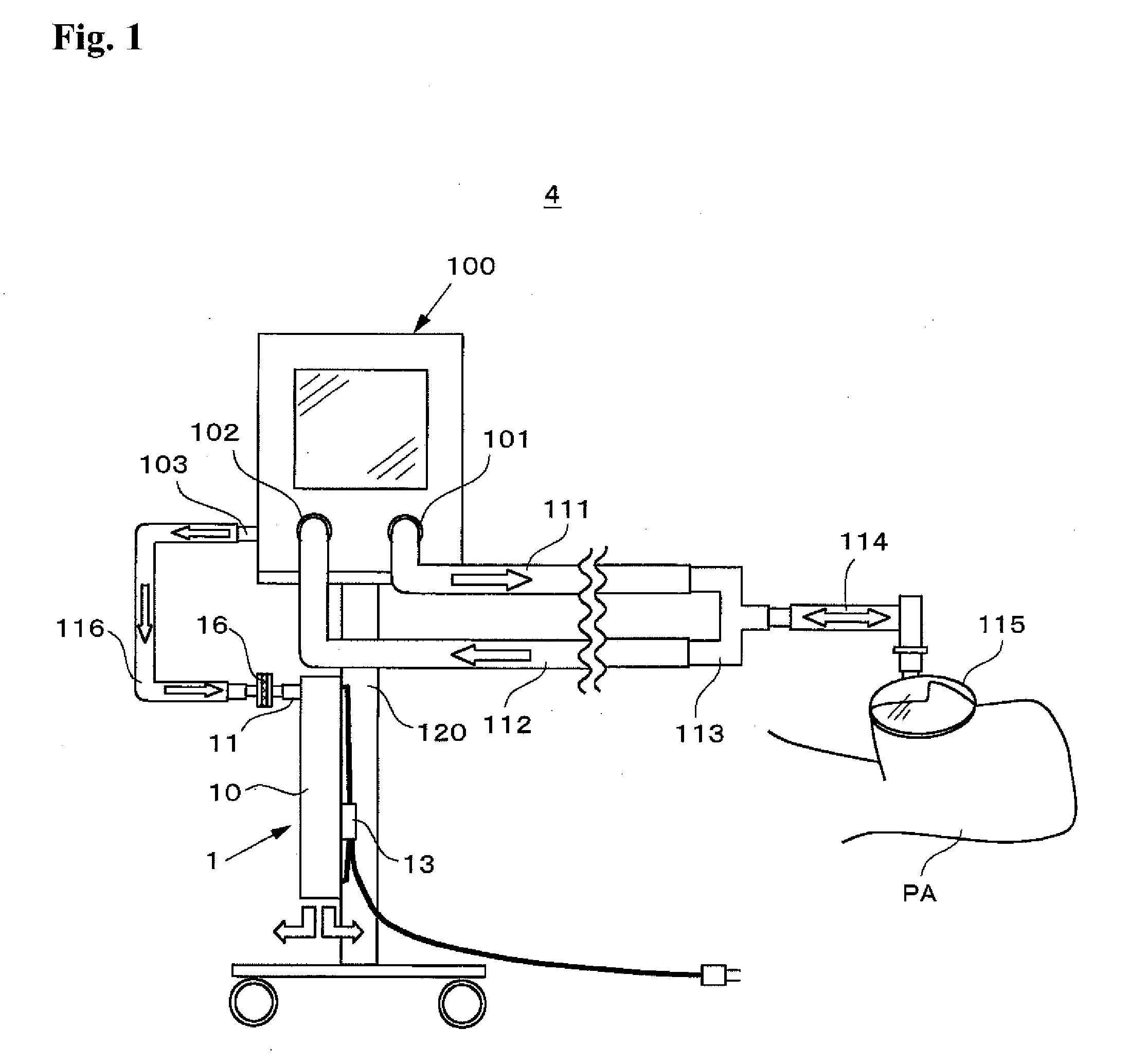
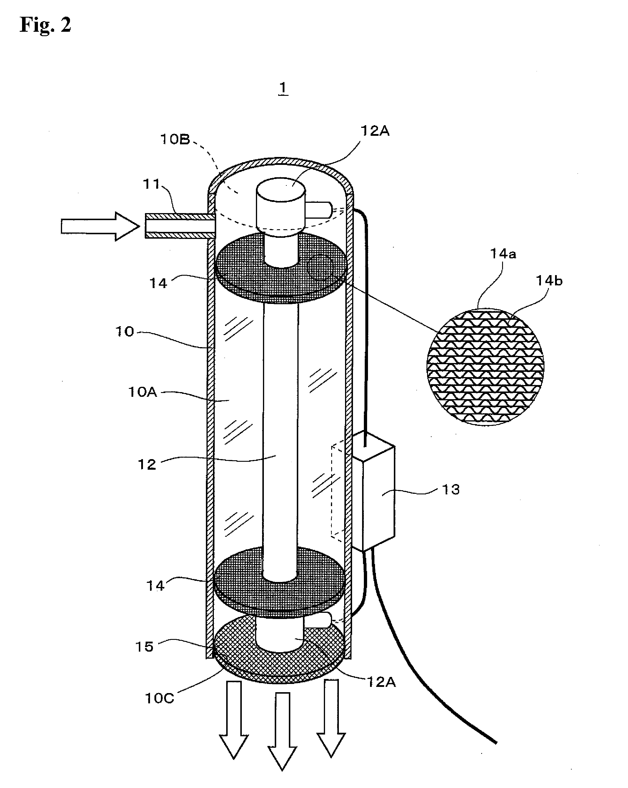
[0073]Firstly, a description is given to an air disinfection and cleaning device according to First Embodiment of the present invention and an exhaled gas disinfection and cleaning device using the same with reference to FIGS. 1 through 3.

[0074]In FIG. 1, an exhaled gas disinfection and cleaning device 4 according to the present embodiment comprises a ventilator 100 to control inhalation and exhalation of a patient PA, a stand 120 to place the ventilator 100 thereon, a breathing circuit to be a flow path of an inhalation gas and an exhalation gas, and an air disinfection and cleaning device 1 to disinfect and clean an exhaled gas of the patient PA.

[0075]The ventilator 100 is connected to an oxygen blender, not shown. This oxygen blender mixes compressed air and compressed oxygen to generate an inhalation gas having an oxygen concentration from 21% (air) to 100% (pure oxygen). The ventilator 100 opens an inhalation valve, not shown, based on a decrease in the pressure due to a respir...

second embodiment

[0097]Next, a description is given to an air disinfection and cleaning device according to Second Embodiment of the present invention and an exhaled gas disinfection and cleaning device using the same with reference to FIG. 4.

[0098]In FIG. 4, like components as in First Embodiment described above are referred to by an identical reference numeral and a detailed description is omitted. The inhalation gas tube connection port 101 and the exhalation gas tube connection port 102 of the ventilator 100 illustrated in this drawing are considered to be connected to a breathing circuit similar to that of First Embodiment described above and they are omitted from the illustration.

[0099]In FIG. 4, an exhaled gas disinfection and cleaning device 5 in the present embodiment is configured with an air disinfection and cleaning device 2 connected to the exhalation gas exhaust port 103 of the ventilator 100 via a reservoir bag 131 to maintain a constant flow rate of an exhalation gas passing through ...

third embodiment

[0109]A description is given to an air disinfection and cleaning device according to Third Embodiment of the present invention with reference to FIG. 5.

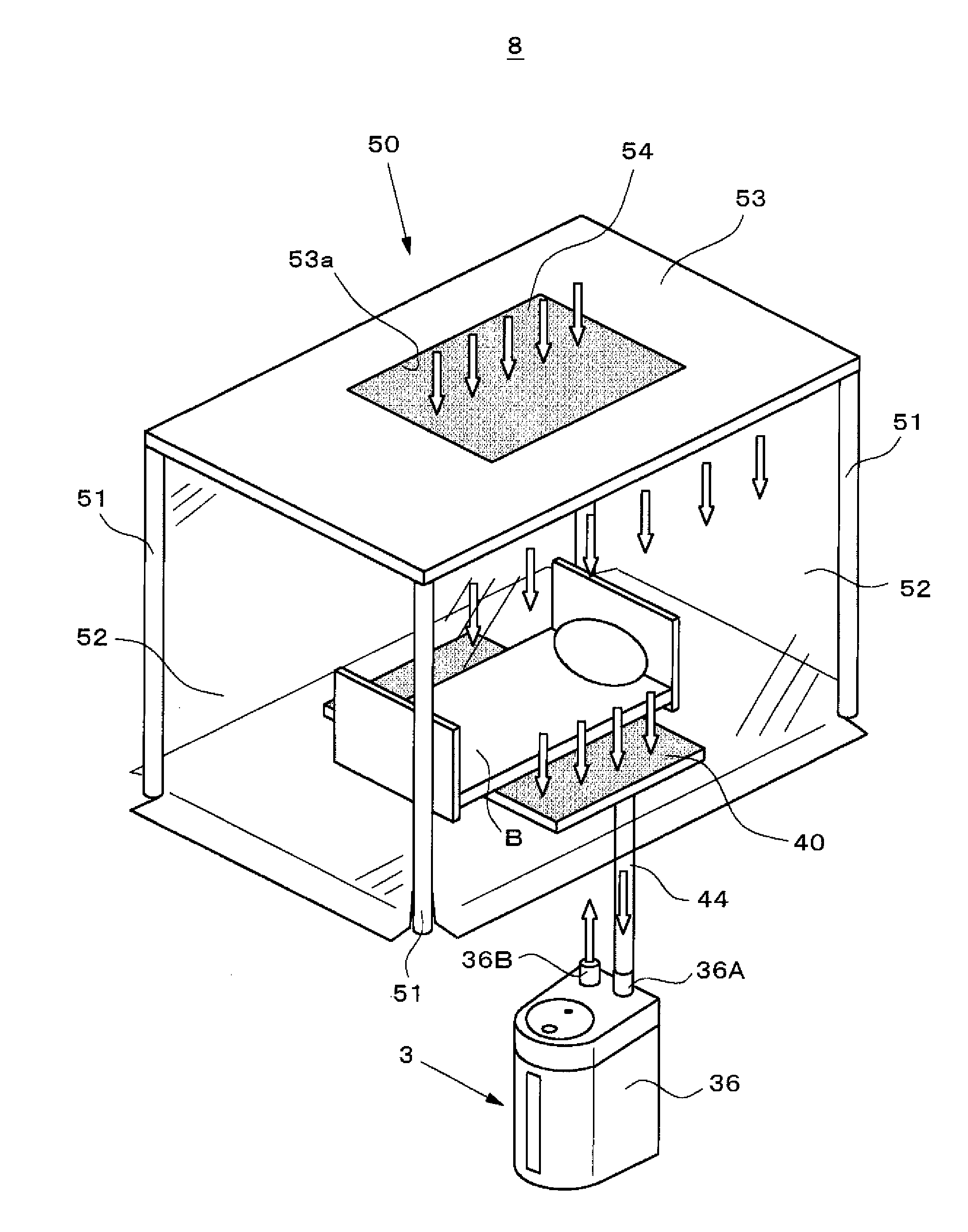
[0110]As illustrated in FIG. 5, an air disinfection and cleaning device 3 in the present embodiment is configured with a plurality of air disinfection and cleaning devices 3A, 3B, 3C, 3D coupled in series, these air disinfection and cleaning devices 3A through 3D stored in a housing 36.

[0111]The cylindrical reflector 30 of each of the air disinfection and cleaning devices 3A through 3D is made with a cylindrical member with both upper and lower ends as closures 30A, 30B, and the upper and lower ends of the respective cylindrical reflectors 30 are coupled in series via pipelines 33, 33, 33 capable of air distribution. Although not shown, inside each cylindrical reflector 30, similar to the air disinfection and cleaning device 2 in FIG. 4, the ultraviolet lamp 12, the two photocatalytic sheet filters 14, 14, and one copper sheet filter...


PUM

PropertyMeasurementUnit
timeaaaaaaaaaa
diameteraaaaaaaaaa
inner diameteraaaaaaaaaa

Abstract

An air disinfection and cleaning device is provided that includes: a cylindrical reflector having a cylindrical inner surface in which an air flows from an upper end to a lower end and the cylindrical inner surface is subjected to mirror finishing; a rod shaped ultraviolet lamp disposed at the center within the cylindrical reflector parallel to the long side; photocatalytic sheet filters being air permeable photocatalytic sheet filters having a diameter nearly equal to an inner diameter of the cylindrical reflector, provided respectively at one end and the other end in the cylindrical reflector, and being penetrated by the ultraviolet lamp at the center thereof; and a copper sheet filter being an air permeable photocatalytic sheet filter having a diameter nearly equal to an inner diameter of a cylinder member and closing a lower end opening of the cylindrical reflector.

Description

TECHNICAL FIELD[0001]The present invention relates to an air disinfection and cleaning device to disinfect and clean an air in, for example, a hospital room and a consultation room, and an exhaled gas disinfection and cleaning device, an interior air disinfection and cleaning device, and a simplified isolation device using the same, and relates specifically to a simple and compact air disinfection and cleaning device that can obtain high disinfection and cleaning effects with a small volume and a short total length, and an exhaled gas disinfection and cleaning device, an interior air disinfection and cleaning device, and a simplified isolation device using the same.BACKGROUND ART[0002]One of the infection routes of infectious diseases is airborne infection. Airborne infection is to infect a third person by breathing in air floating bacteria dispersed from a patient into the respiratory organs. A general measure to prevent airborne infection is to isolate infected patients in private...

Claims


Application Information

Patent Timeline
Patent Type & Authority Applications(United States)
IPC IPC(8): A61L2/10A62B23/02A61M16/00F24F8/80F24F8/108F24F8/167
CPCA61L9/205A61L2209/14F24F2003/1667F24F3/1603A61L2209/212Y02A50/20F24F8/22F24F8/10F24F8/108F24F8/80F24F8/167
Inventor SATA, YASUHIKOHACHISU, NORIO
Owner TKB
Learn More