
Method and Fuel Composition for Catalytic Heater

a technology of catalytic heaters and fuel compositions, which is applied in the direction of burners, combustion regulation, combustion types, etc., can solve the problems of inefficient combustion of carbon monoxide byproducts, indirect methods, slow and inefficient heating of catalysts,

Inactive Publication Date: 2012-11-08
AIR PROD & CHEM INC
View PDF4 Cites 4 Cited by
  • Summary
  • Abstract
  • Description
  • Claims
  • Application Information

AI Technical Summary

Benefits of technology

[0009]The method and a preheat composition described herein for pre-heating and/or heating a catalytic heater comprising hydrogen satisfies one or more of the needs in the art. In one aspect, there is provided a method of preheating a catalyst in a catalytic heater comprising the steps of: providing a preheat composition comprising greater than 60% by volume hydrogen and at least one sel

Problems solved by technology

Other byproducts such as carbon monoxide can be a result of inefficient combustion.
These indirect methods, whereby the catalyst is preheated by preheating the heater surface, are slow and inefficient.
This will produce a reaction temperature on the heater surface of from about 750° F. to about 1000° F. However, when operating at the lower flow rates, that is, about 2 cubic feet of gas per hour per square foot, the temperature distribution across the heater surface will vary from about 200° F. to about 800° F. This poses many problems particularly when the heaters are used for heating flat areas.
The catalytic heaters develop hot and cold spots across the heating surface and produce an uneven heating profile to the object being heated.
As a consequence, process control is very poor and efficiency is reduced.
Another disadvantage of catalytic heaters is that some of the fuel gas is left unreacted by the catalyst and escapes through the heater into the atmosphere.
In addition to fuel-value loss, methane slip also increases the heater-start time and allows the high-GHG (Green-house gas) value methane to escape into the atmosphere.
According to the '593 patent, this reaction is generally so violent that a stream of 99% pure hydrogen impinging on this layer will create a temperature on the layer that causes the hydrogen stream to burn.

Method used


Image

  • Method and Fuel Composition for Catalytic Heater
  • Method and Fuel Composition for Catalytic Heater

Examples


examples

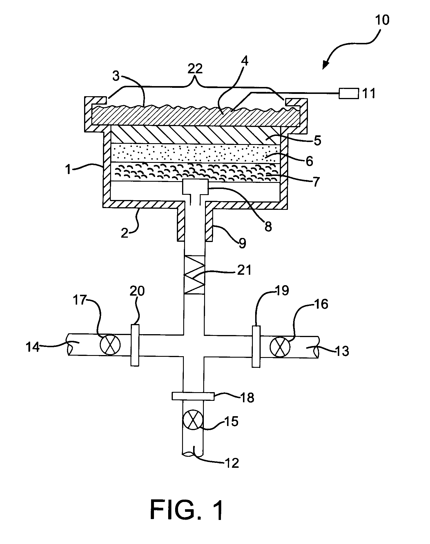
[0027]The following examples illustrate the ability to use the method and preheat compositions described herein to preheat a typical catalytic heater. A series of tests were conducted whereby the catalytic heater was preheated using different preheat compositions described in Table 1. The tests were conducted using a catalytic heater from Vulcan Catalytic Systems to illustrate the reduced methane slip and the homogeneous surface temperature benefits of the preheat composition and method described herein. The catalytic heater was mounted in a vertical orientation at the center of a ventilated enclosure with a known constant ventilation rate for the purpose of the tests. The vertical mount facilitated capturing images of the heater surface. The catalytic heater inlet was connected to a flow skid that is capable of metering a supply of hydrogen at a certain flow rate or a fuel composition containing one or more of the following components: hydrogen, nitrogen and natural gas at a specif...

examples 1 through 5

[0034]In Example 1, the catalytic heater preheats gas composed of 62% hydrogen and 38% natural gas is supplied to the catalytic heater for two minutes. The hydrogen gas supply is shut off and the natural gas flow is increased to maintain a constant flow of gas through the heater.

[0035]In Example 2, the catalytic heater preheat gas composed of 100% hydrogen is supplied to the catalytic heater for two minutes. The hydrogen gas supply is shut off and the natural gas supply is turned on at a flow rate that maintains a constant flow of gas through the heater.

[0036]In Example 3, the catalytic heater preheat gas composed of 100% hydrogen is supplied to the catalytic heater for three minutes. The hydrogen gas supply is shut off and the natural gas supply is turned on at a flow rate that maintains a constant flow of gas through the heater.

[0037]In Example 4, the catalytic heater preheat gas composed of 100% hydrogen is supplied to the catalytic heater for four minutes. The hydrogen gas suppl...


PUM


Abstract

A method and fuel composition for pre-heating and / or operating a catalytic heater is described herein. In one aspect, there is provided a method of preheating a catalyst in a catalytic heater comprising the steps of: providing a preheat composition comprising greater than 60% by volume hydrogen and at least one fluid component selected from natural gas, propane, butane, refinery off gas, ethylene off gas, methanol, ethanol, butanol, liquefied biogas and mixtures thereof; and contacting the catalyst with the preheat composition for a period of time sufficient to raise the temperature of the catalyst to a one or more temperatures. In this or other embodiments, there is a fuel composition that comprises at least one component selected from natural gas, propane, butane and mixtures thereof and optionally hydrogen.

Description

CROSS-REFERENCE TO RELATED APPLICATIONS[0001]This patent application claims the benefit of provisional patent application U.S. Ser. No. 61,415,124, entitled “Method and Fuel Composition for Catalytic Heater” filed Nov. 18, 2010 and provisional patent application U.S. Ser. No. 61 / 422,780, entitled “Method and Fuel Composition for Catalytic Heater” filed Dec. 14, 2010, the disclosures of which are incorporated herein by reference.BACKGROUND OF THE INVENTION[0002]Described herein is a method and composition for pre-heating and / or heating a catalytic heater.[0003]Catalytic heaters are well suited for hazardous or other environments. These heaters use infrared heat to provide a uniform, low intensity, non-glowing heat. The catalytic heater produces infrared energy in the form of a long to medium wavelength energy which allows it to be readily absorbed by a wide range of materials. In a catalytic heater, infrared heat is produced when a gaseous fuel is brought into contact with a catalyst...

Claims


Application Information

Patent Timeline
IPC IPC(8): F23D14/18F23Q13/00
CPCF23D14/18F23Q13/00F23Q11/00
Inventor JOHNSON, LEIGHTA MAUREEN
Owner AIR PROD & CHEM INC
Learn More