
Partial discharge analysis coupling device

a coupling device and partial discharge technology, applied in the direction of testing circuits, instruments, pulse characteristics measurement, etc., can solve the problem of difficulty in partial discharge analyzers to analyze pulse signals

Active Publication Date: 2012-11-08
GENERAL ELECTRIC CO
View PDF2 Cites 3 Cited by
  • Summary
  • Abstract
  • Description
  • Claims
  • Application Information

AI Technical Summary

Benefits of technology

[0004]Aspects of the invention provide for a partial discharge analysis (PDA) coupling device. In one embodiment, aspects of the invention include a device comprising: a connector electrically connecting a first coupling capacitor and a second coupling capacitor; a first conductive rod for electrically connecting the first coupling capacitor to a high voltage input; a second conductive rod for electrically connecting the second coupling capacitor to ground; a current transformer substantially surrounding a portion of the second conductive rod, the current transformer configured to generate a pulse signal; and a reference signal generator adjacent to the current transformer configured to generate

Problems solved by technology

However, the reference signal is usually not “in phase” with the pulse signal, which makes it difficult for the partial discharge analyzer to analyze the pulse signal.

Method used


Image

  • Partial discharge analysis coupling device
  • Partial discharge analysis coupling device
  • Partial discharge analysis coupling device

Examples


Embodiment Construction

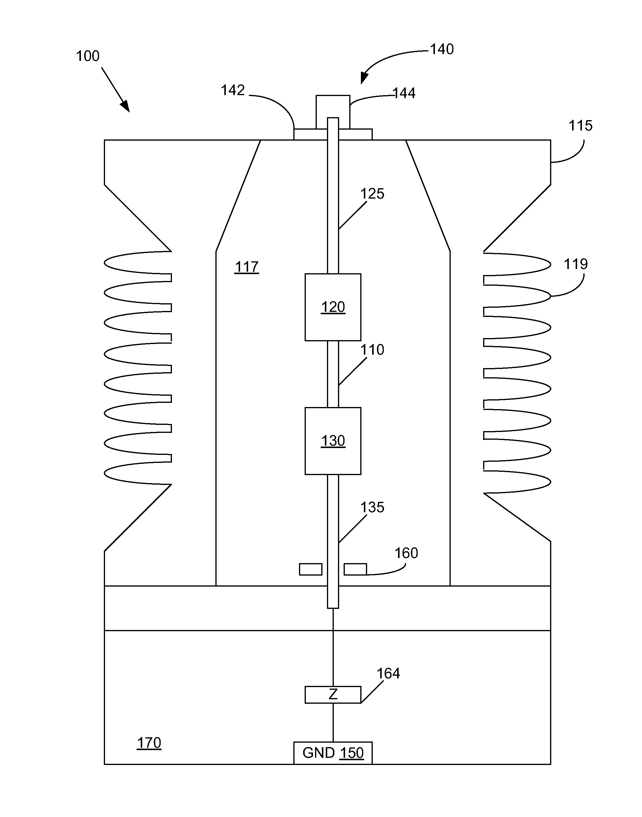
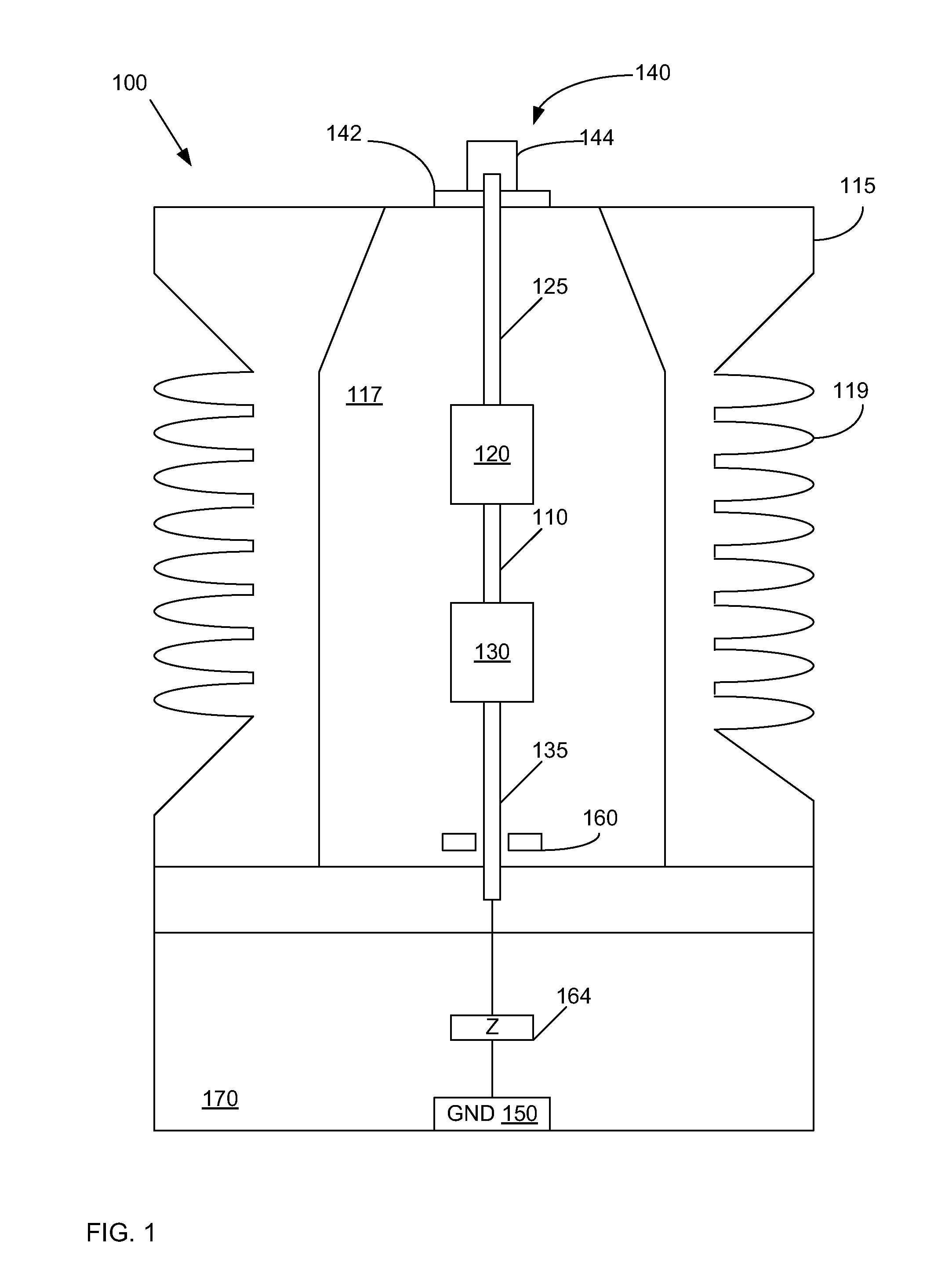
[0014]Turning to FIG. 1, a cross-sectional view of a partial discharge analysis (PDA) coupling device 100 according to an embodiment of the invention is shown. PDA coupling device 100 includes a casing 115 comprising a cavity 117. Casing 115 may include any now known or later developed insulating material, such as, but not limited to aluminum trihydrate, polycarbonate, or epoxy, such as glass-filled cycloaliphatic epoxy. Cavity 117 may be filled with an electrical potting material (not shown). The electrical potting material may be any now known or later developed encapsulating material, such as, but not limited to, filled or unfilled polyurethane, silicone, epoxy, a mixture of mica and epoxy, polyester, ethylene propylene rubber (EPR), or fluorocarbon or perfluorocarbon.

[0015]Casing 115 may be substantially cylindrical in shape and include a plurality of ribs 119 on its outer surface. However, it is understood that casing 115 may be any other desired shape. Further, although cavity...


PUM


Abstract

A partial discharge analysis (PDA) coupling device is provided. In one embodiment, a device includes: a connector electrically connecting a first coupling capacitor and a second coupling capacitor; a first conductive rod for electrically connecting the first coupling capacitor to a high voltage input; a second conductive rod for electrically connecting the second coupling capacitor to ground; a current transformer substantially surrounding a portion of the second conductive rod, the current transformer configured to generate a pulse signal; and a reference signal generator adjacent to the current transformer configured to generate a reference signal in phase with the pulse signal.

Description

BACKGROUND OF THE INVENTION[0001]The subject matter disclosed herein relates generally to electrical coupling devices. More specifically, the present disclosure relates to partial discharge analysis (PDA) coupling devices that generate a pulse signal and a reference signal.[0002]A partial discharge analyzer is an instrument that is used to measure partial discharge on rotating machines, such as motors and generator stator systems. In one example, the partial discharge analyzer is used to monitor the degradation of the insulation within the generator stator windings.[0003]A PDA coupling device is electrically connected to the machine being monitored by the partial discharge analyzer and the partial discharge analyzer. For example, one end of the PDA coupling device (i.e., the high voltage side) may be connected to the leads of the generator stator windings and the opposite end of the PDA coupling device may be connected to ground. The PDA coupling device generates a pulse signal that...

Claims


Application Information

Patent Timeline
IPC IPC(8): G01R27/26H01F38/28
CPCG01R31/1272G01R31/14G01R31/1227G01R29/02G01R27/02
Inventor KERL, JAMES EDWARDZHOU, YINGNENGYOUNSI, KARIM
Owner GENERAL ELECTRIC CO
Learn More