
Muffler of internal combustion engine

Active Publication Date: 2012-10-25
SUZUKI MOTOR CO LTD
View PDF23 Cites 1 Cited by
  • Summary
  • Abstract
  • Description
  • Claims
  • Application Information

AI Technical Summary

Benefits of technology

[0011]Thus, in view of the above-described circumstances, an object of the present invention is to provide a muffler of an internal combustion engine enabling a smooth sampling inspection of exhaust gas and capable of sufficiently suppressing an occurrence of an abnormal noise such as a whistling sound while satisfying demand of design.

Problems solved by technology

However, by only performing a processing described above to the tail pipe, it is difficult to sufficiently suppress the vibration of the air occurring in the space between the tail pipe and the tail cover, and a suppressing effect of the abnormal noise occurrence is limited.
Though narrowing the gap between the tail cover and the tail pipe enables prevention of the abnormal noise occurrence, in such a case it is hard to insert a tube in the above-described gap at a time of the exhaust gas sampling inspection, and the exhaust gas sampling inspection becomes troublesome.
Further, extending the tail pipe more rear than the tail cover similarly enables prevention of the occurrence of the abnormal noise, but in such a case the rear end portion of the tail pipe is exposed from the tail cover, unsatisfying demand of design.

Method used


Image

  • Muffler of internal combustion engine
  • Muffler of internal combustion engine
  • Muffler of internal combustion engine

Examples


first embodiment

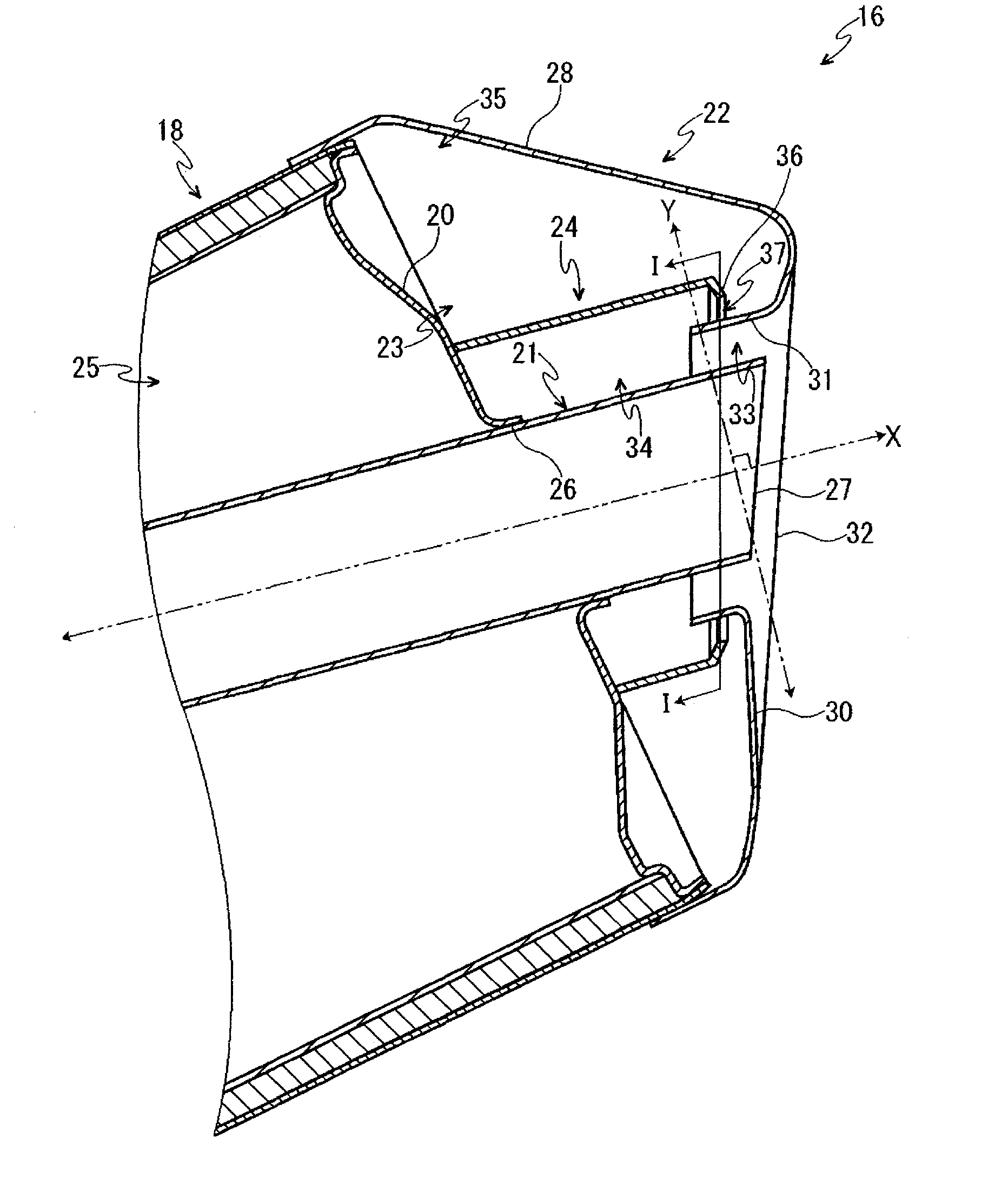
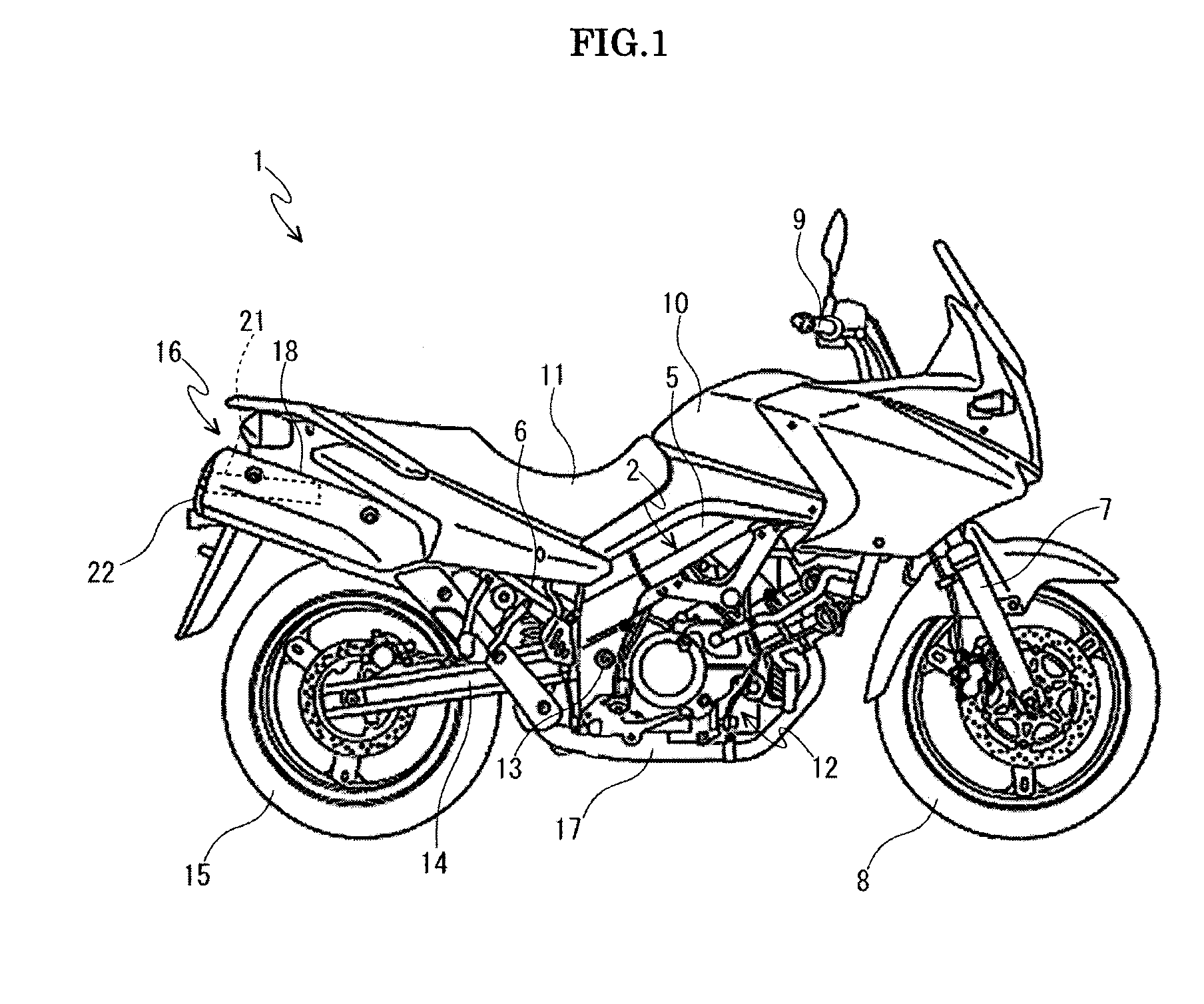
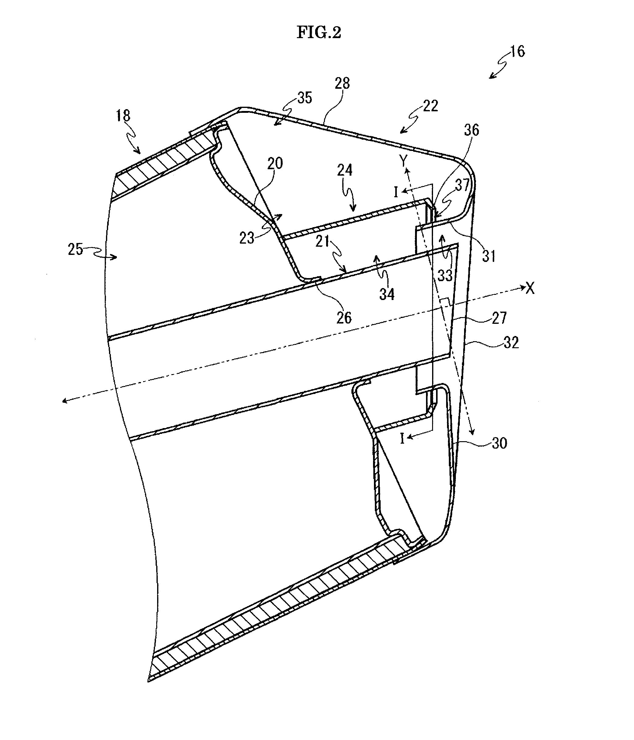
[0032]The first embodiment of the present invention will be described, with reference to FIG. 1 to FIG. 3. First, an entire constitution of the motorcycle 1 will be described by using FIG. 1.

[0033]The motorcycle 1 is provided with a vehicle body frame 2 constituting a framework. The vehicle body frame 2 is, for example, of a twin-tube type and is constituted mainly by a head pipe (not shown) disposed in a front portion upper end of the vehicle body frame 2, a right and left pair of main frames 5 extended from the head pipe to rear downward, and a right ant left pair of seat rails 6 extended from rear portions of the main frames 5 to rear upward.

[0034]A right and left pair of front forks 7 is supported by the head pipe rotatably in right and left directions. A front wheel 8 is pivotally supported by a lower end of the front fork 7, and a handle bar 9 is supported by an upper end of the front fork 7.

[0035]A fuel tank 10 is provided between the right and left pair of main frames 5, a d...

second embodiment

[0056]Next, the second embodiment of the present invention will be described by using FIG. 4. It should be noted that since constitutions of members except a tail cover 22 and a partition wall 24 are similar to those in the first embodiment, explanation thereof will be omitted.

[0057]The tail cover 22 has a peripheral wall portion 28 covering an outer periphery of a tail pipe 21, a rear wall portion 30 extended from a rear end of the peripheral wall portion 23 toward an inner side, and a fold portion 31 folded from an upper portion of the rear wall portion 30 toward the front, and a partition wall 24 is integrally formed with the fold portion 31 in a manner to be extended from the fold portion 31 toward the front. Between a front end portion of the partition wall 24 and a rear end surface 20 of the muffler main body 18 is provided a space communication portion 37 communicating an inner side space 34 and an outer side space 35.

[0058]In the present embodiment, since the partition wall ...

third embodiment

[0059]Next, the third embodiment of the present invention will be described by using FIG. 5. It should be noted that since constitutions of members except a partition wall 24 are similar to those in the first embodiment, explanation thereof will be omitted.

[0060]The partition wall 24 has a mounting plate 41 having a through hole 40 bored in a center and having a ring shape, and a flange 42 protruding from an outer periphery of the mounting plate 41 toward the rear. An inner periphery part of the through hole 40 of the mounting plate 41 is welded to an outer peripheral surface of the tail pipe 21. The flange 42 is disposed to overlap with a fold portion 31 in a direction Y orthogonal to a longitudinal, direction X of a tail pipe 21. In other words, the fold portion 31 is provided in a state to be inserted between the tail pipe 21 and the flange 42.

[0061]As described above, by welding the mounting plate 41 of the partition wall 24 to the outer peripheral surface of the tail pipe 21, i...


PUM


Abstract

A muffler of an internal combustion engine is characterized in that a muffler of an internal combustion engine having a muffler main body connected to a rear end of an exhaust pipe of the internal combustion engine, a tail pipe extended from a rear end surface of the muffler main body, and a tail cover covering an outer periphery of the tail pipe includes a partition wall compartmentalizing a space formed between the tail pipe and the tail cover into at least two or more spaces.

Description

CROSS-REFERENCE TO RELATED APPLICATION[0001]This application is based upon and claims the benefit of priority of the prior Japanese Patent Application No. 2011-093727, filed on Apr. 20, 2011, the entire contents of which are incorporated herein by reference.BACKGROUND OF THE INVENTION[0002]1. Field of the Invention[0003]The present invention relates to a muffler of an internal, combustion engine used for a vehicle such as a motorcycle and an automobile.[0004]2. Description of the Related Art[0005]Conventionally, in a vehicle such as a motorcycle and an automobile, exhaust as from an internal combustion engine is discharged to the rear of the vehicle via a muffler. The above-described muffler usually has a muffler main body forming one or a plurality of sound-deadening chamber(s) and a tail pipe extended from a rear end surface of the muffler main body. Thus, it is so constituted that the exhaust gas from the inner combustion engine passes through the noise-deadening chamber of the m...

Claims


Application Information

Patent Timeline
IPC IPC(8): F01N13/08
CPCF01N2590/04F01N13/082
Inventor IIYAMA, TADASHIMATSUSHITA, KENJI
Owner SUZUKI MOTOR CO LTD
Learn More