
Method and Apparatuses for Data Transfer within a Relay Enhanced Telecommunication Network

a technology of enhanced telecommunication network and relay system, which is applied in the field of relay enhanced telecommunication network, can solve the problems of unwanted feedback contribution to the total received dl radio signal, deterioration of the radio signal quality of the donor bs, and affecting the data transfer speed of the relay system, so as to achieve the effect of maximizing the data throughput between the relay system and the respective u

Inactive Publication Date: 2012-10-04
WSOU INVESTMENTS LLC
View PDF5 Cites 47 Cited by
  • Summary
  • Abstract
  • Description
  • Claims
  • Application Information

AI Technical Summary

Benefits of technology

[0031]According to an embodiment of the invention the first user equipment is served by the relay system with a first spatial radiation pattern and the second user equipment is served by the relay system with a second spatial radiation pattern being different from the first spatial radiation pattern. This may provide the advantage that a spatial differentiation between the two UEs can be realized for instance by applying an appropriate beamforming. Thereby, the overall data throughput within the radio telecommunication network may be increased.
[0072]According to a further embodiment of the invention the method further comprises configuring sub-frames as normal data sub-frames instead of MBSFN sub-frames, if the first and the second self interference and the first and the second backhaul-to-access interference are smaller than a predetermined work point of the relay system. This may provide the advantage that in case the mentioned interferences are comparatively small further radio transmission resources can be exploited for transferring user data. Thereby, the overall data throughput may be further increased.

Problems solved by technology

In this context self interference may mean that when the relay system simultaneously (a) transmits a downlink (DL) radio signal to a connected UE and (b) receives a DL radio signal from its donor BS, at least a portion of the transmitted radio signal may be received by the relay system causing an unwanted feedback contribution to the total received DL radio signal.
As a consequence the quality of the radio signal from the donor BS may be deteriorated.
Correspondingly, a relay system self interference may occur if the relay system simultaneously (a) transmits an uplink (UL) radio signal to its donor BS and (b) receives an UL radio signal from a connected UE such that at least a portion of the transmitted radio signal is received by the relay system causing an unwanted feed-back contribution to the total received UL radio signal.
As a consequence, the quality of the radio signal from the UE may be deteriorated.

Method used


Image

  • Method and Apparatuses for Data Transfer within a Relay Enhanced Telecommunication Network
  • Method and Apparatuses for Data Transfer within a Relay Enhanced Telecommunication Network
  • Method and Apparatuses for Data Transfer within a Relay Enhanced Telecommunication Network

Examples


Embodiment Construction

[0093]The illustration in the drawing is schematically. It is noted that in different figures, similar or identical elements are provided with the same reference signs or with reference signs, which are different from the corresponding reference signs only within the first digit.

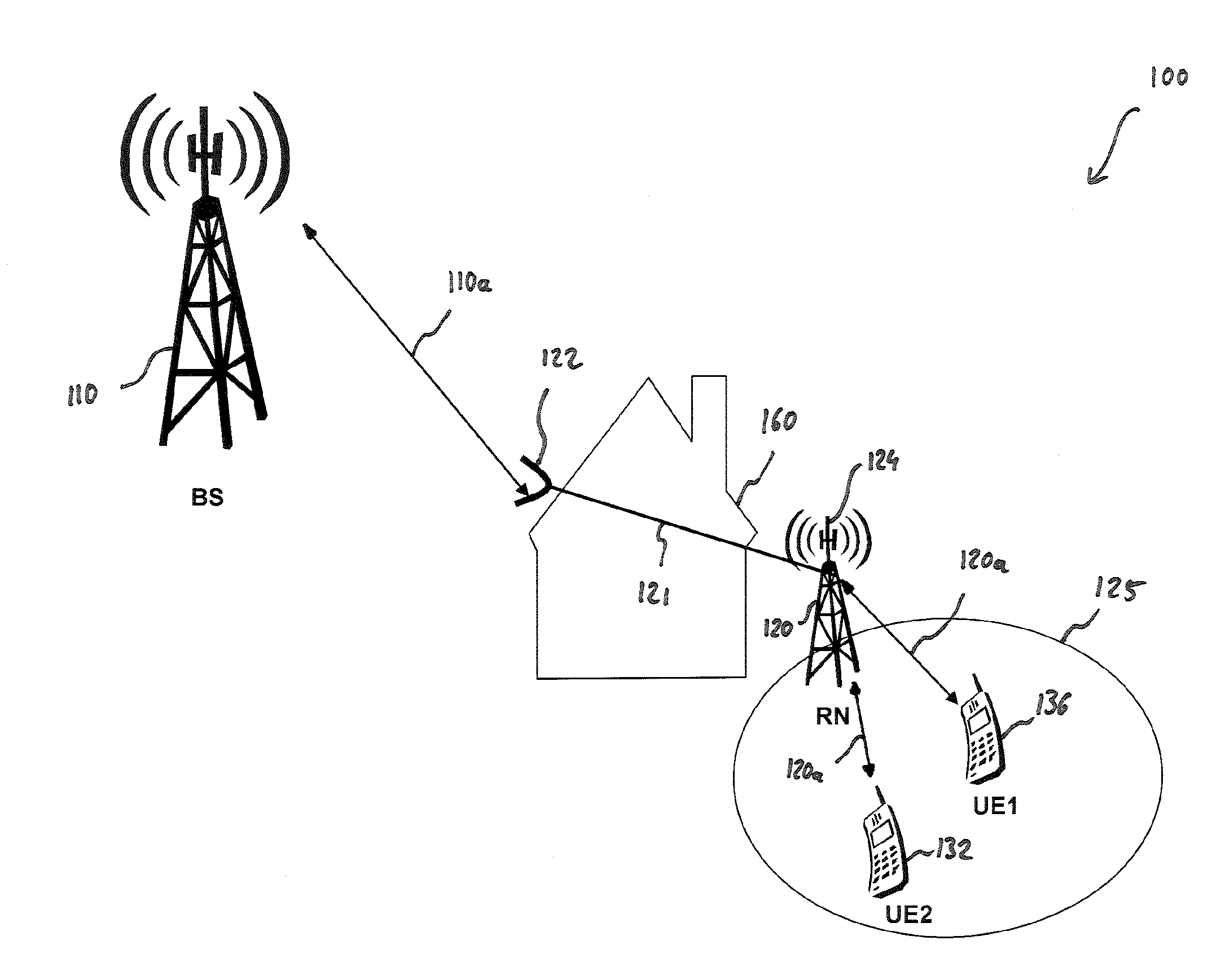
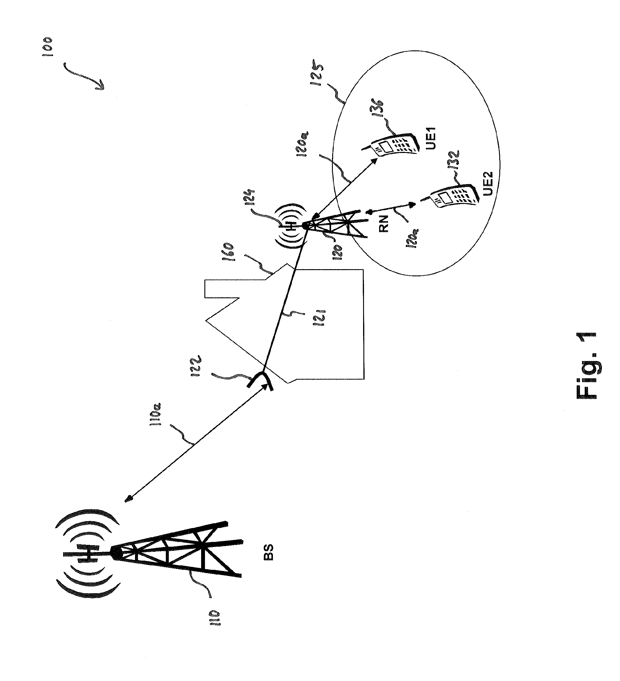
[0094]FIG. 1 shows a relay enhanced telecommunication network 100 operating in accordance with an embodiment of the present invention. The network 100 comprises a base station (BS) 110 and a relay node (RN) 120. The BS 110 and the RN 120 are connected via a radio link 110a, which is called a relay link or a backhaul link. The RN 120 serves a relay cell 125. The network 100 further comprises two user equipments, a first user equipment (UE) 136 and a second UE 132. The two UEs 136 and 132 are both connected to the RN 120 via radio links 120a. These radio links 120a are also called access links.

[0095]As can be seen from FIG. 1, the RN 120 is located close to an object, which represents a barrier for the propaga...


PUM


Abstract

A method for scheduling a first user equipment, UE, with a first performance causing a first self interference of a relay system between a first access link extending between the relay system and the first UE and a relay link extending between the relay system and a base station, BS, and scheduling a second UE with a second performance causing a second self interference of the relay system between a second access link extending between the relay system and the second UE and the relay link extending between the relay system and the BS. Thereby, if the first self interference is larger than the second self interference, the first performance is smaller than the second performance. Alternatively, if the first self interference is smaller than the second self interference, the first performance is larger than the second performance.

Description

FIELD OF INVENTION[0001]The present invention relates to the field of relay enhanced telecommunication network. Specifically, the present invention relates to a method for transferring data within a radio telecommunication network comprising a base station, a relay system, a first user equipment and a second user equipment. Further, the present invention relates to a relay system and to a base station which are adapted for controlling the mentioned data transfer method.ART BACKGROUND[0002]A cost efficient solution for improving the performance of Long Term Evolution (LTE) and LTE-Advanced (LTE-A) telecommunication networks can be the utilization of relay nodes (RN), which allows installations without having terrestrial broad-band access or the need to install a micro wave link. In a relay enhance network there are basically three different types of connections: (A) A first type is the connection between a base station (BS), which in Long Term Evolution (LTE) technology is called an ...

Claims


Application Information

Patent Timeline
Patent Type & Authority Applications(United States)
IPC IPC(8): H04W88/04H04W24/00H04B3/36
CPCH04B7/2606H04W72/082H04B7/15564H04W84/047H04B7/15557H04W72/1231H04W72/542H04W72/541
Inventor ZHAO, ZHU YANREDANA, SIMONERAAF, BERNHARD
Owner WSOU INVESTMENTS LLC
Learn More