
System for controlling battery conditions

a battery condition and system technology, applied in the field of system for controlling battery conditions, can solve the problems of increased voltage drop between the cell and the load, reduced battery effective to supply sufficient power, high cost and larger package size, etc., to achieve the effect of increasing the size and/or capacity of the battery, increasing the cost and/or the capacity of the battery

Active Publication Date: 2012-10-04
CONTINENTAL AUTOMOTIVE SYST INC
View PDF12 Cites 32 Cited by
  • Summary
  • Abstract
  • Description
  • Claims
  • Application Information

AI Technical Summary

Benefits of technology

[0007]One solution to this problem would be to increase the size and / or capacity of the battery. The main drawback of this is primarily a high cost and larger package size. For an automotive ECALL application, having a smaller package size and lower cost is a distinct advantage.
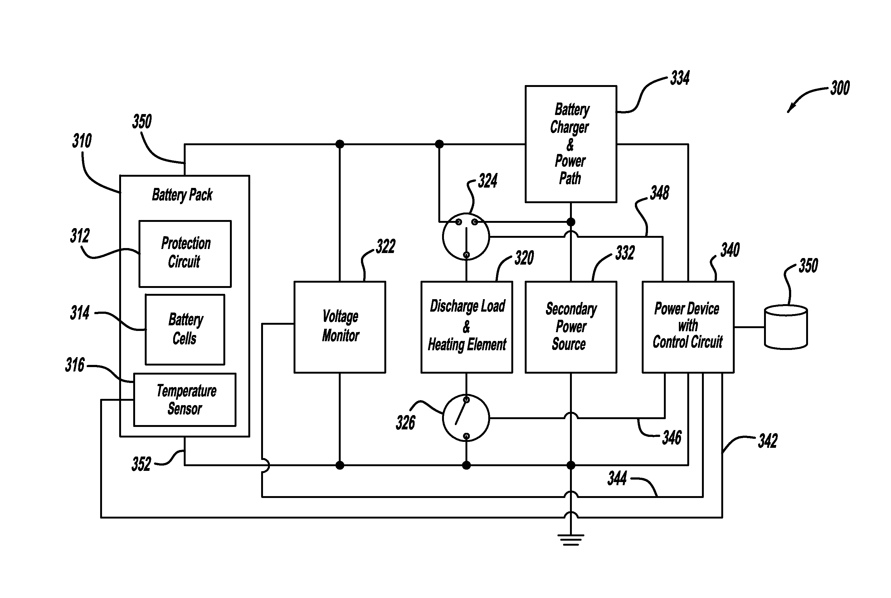
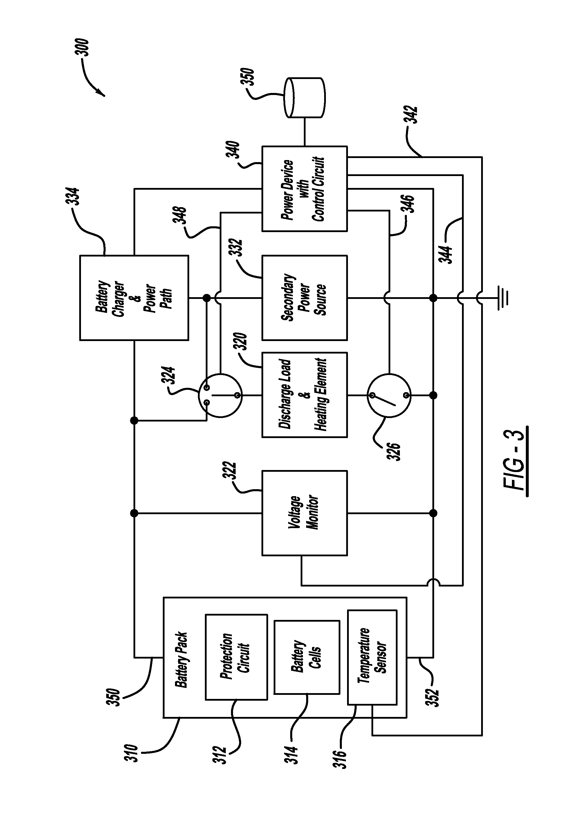
[0012]For an ECALL application, it is possible that the event that triggers the call could occur some short period of time after the vehicle has been running. In this case, the heating element can be powered from the vehicle's alternator as the secondary power source so that the maximum capacity of the back up battery can be obtained. As part of the power path management, a switch is used to connect the heating element to either the secondary power source or to the battery pack.

Problems solved by technology

However, the effectiveness of a battery to supply sufficient power is diminished when the temperature of the battery is close to or below 0° C. The lower temperature increases the output impedance of the battery causing increased voltage drop between the cell and the load when the load current increases.
The main drawback of this is primarily a high cost and larger package size.
If the heater is activated only when the ignition switch is in the RUN position, there will be a delay before the back up battery is warmed sufficiently to complete a call.

Method used


Image

  • System for controlling battery conditions
  • System for controlling battery conditions
  • System for controlling battery conditions

Examples


Embodiment Construction

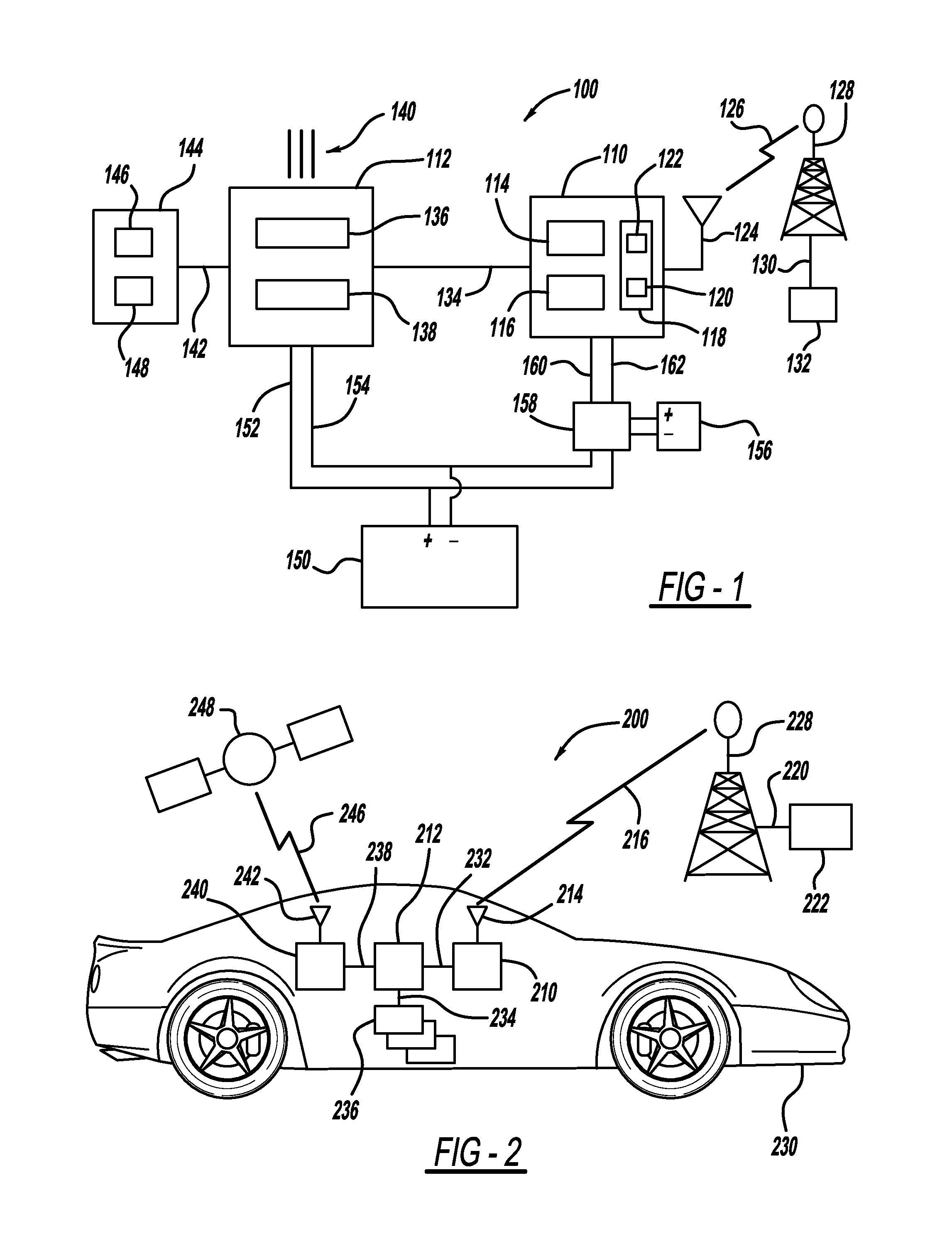
[0022]Now referring to FIG. 1, a system 100 is provided. The system includes a network access device 110 and a telematics controller 112. The network access device 110 may include a processor 114 and storage 116. The processor 114 may be a programmable microprocessor or alternatively may be an application specific integrated circuit (ASIC), or other known processor. The storage 116 may be a memory, for example, random access memory, static memory, or other data storage device. The network access device 110 may also include a transceiver 118 which includes a transmitter 122 and a receiver 120. Alternatively, the network access device 110 may include an independent transmitter and receiver. The transceiver 118 may be in communication with an antenna 124. The transceiver 118 may communicate with a radio tower 128 as denoted by line 126. The communication 126 between the network access device 110 and the radio tower 128 may comprise one of a plurality of communication modes.

[0023]The tr...


PUM


Abstract

A system and method for controlling battery conditions. The system includes a network access device battery. The network access device battery powers a network access device. A heating element may be connected to the network access device battery. The heating element may be a resistive load for determining a status of the network access device battery or the heating element may be activated based on a heating schedule.

Description

BACKGROUND[0001]1. Field of the Invention[0002]The present invention generally relates to a system for controlling battery conditions.[0003]2. Description of Related Art[0004]Often network access devices, such as those associated with vehicle telematics systems, will need to operate in emergency situations. This functionality may be necessary whether or not the vehicle power systems are functioning or even connected. Accordingly, back up batteries are typically provided for these network access devices.[0005]However, the effectiveness of a battery to supply sufficient power is diminished when the temperature of the battery is close to or below 0° C. The lower temperature increases the output impedance of the battery causing increased voltage drop between the cell and the load when the load current increases. Depending on the battery chemistry, this effect may be more pronounced.[0006]The effect of this increased impedance is to reduce the available talk time as the ambient temperatu...

Claims


Application Information

Patent Timeline
Patent Type & Authority Applications(United States)
IPC IPC(8): G05B23/00
CPCH01M10/44H02J7/14H01M10/46H01M10/48H01M10/486H01M10/5006H01M10/5016H01M10/502H01M10/5083H01M10/5097H02J7/1423H02J7/1438B60L11/1842B60L11/1824B60L11/1844H01M10/443H01M10/615H01M10/625H01M10/63H01M10/6571H01M10/667B60L2240/545H02J7/0063B60L58/27Y02T10/70Y02E60/10H02J7/0048H02J7/007194H02J9/06
Inventor ALMQUIST, EDWARDKRAJCI, MARTINBLASKO, JAMES
Owner CONTINENTAL AUTOMOTIVE SYST INC
Learn More