
Branch and Truncal Vessel Occluder

a truncated vessel and occluder technology, applied in the field of implants, can solve the problems of varicose veins and superficial venous insufficiency, blood from the deep system into the superficial system, and high device cost, and achieve the effects of preventing recurrence, and reducing the risk of recurren

Inactive Publication Date: 2012-09-27
DRASLER WILLIAM JOSEPH
View PDF2 Cites 36 Cited by
  • Summary
  • Abstract
  • Description
  • Claims
  • Application Information

AI Technical Summary

Benefits of technology

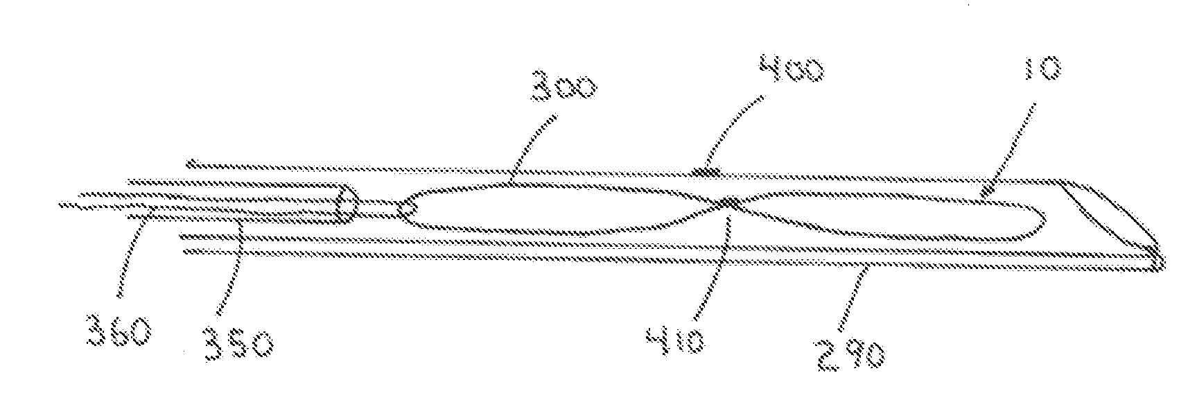
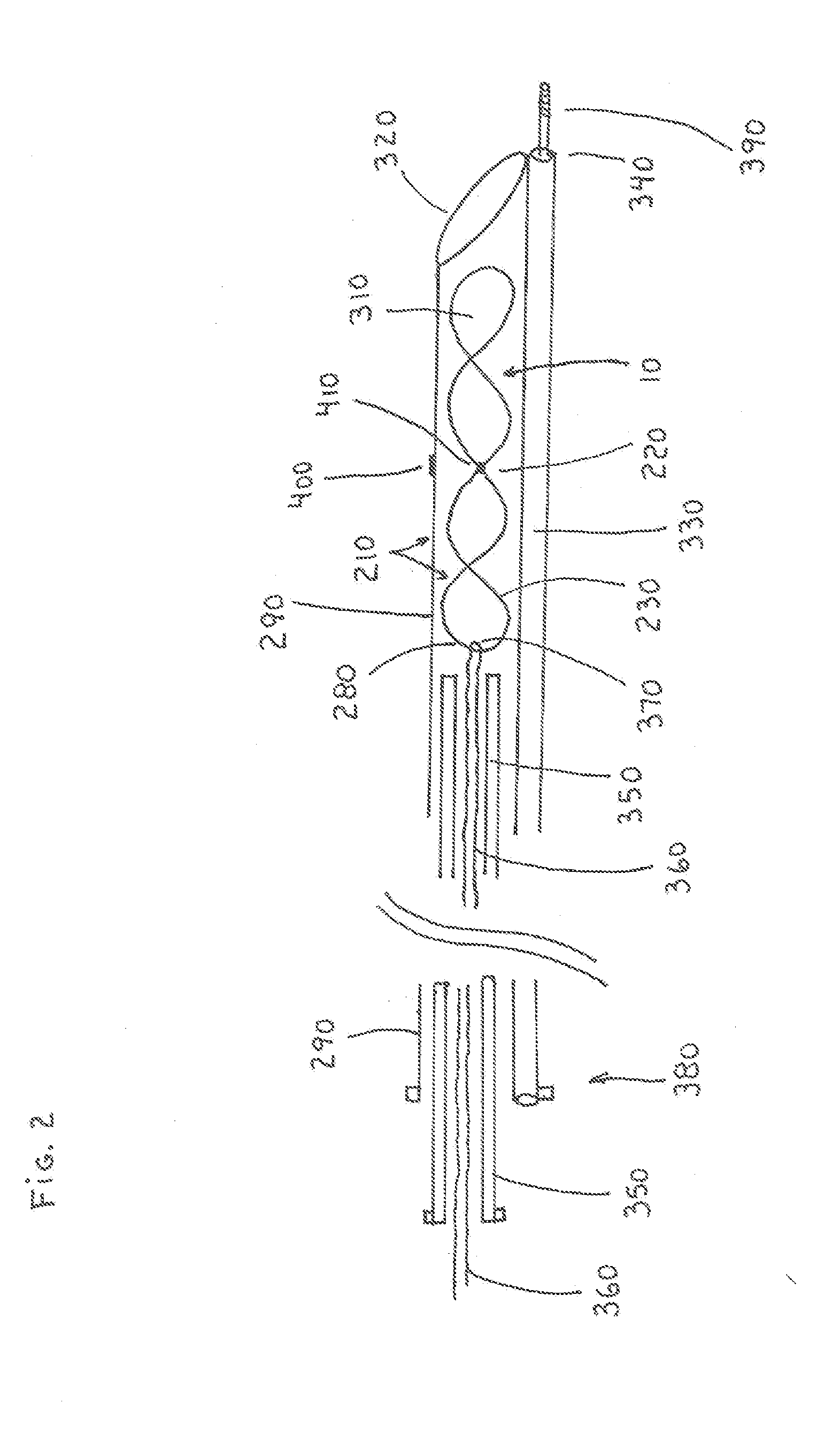
[0011]The frame of the present invention has a very low profile in its non-deployed configuration consisting of two frame members or wires that are aligned adjacent to each other. The low profile associated with these two wires along with their very large flexibility allows the present occlusion device to enter into small diameter veins and achieve a turn from one vein into another.
[0012]One embodiment also has a second truncal portion attached to the branch portion that is intended to be delivered to the truncal vein such as the saphenous vein to which the perforator vein is joined. The truncal portion is also formed of a Nitinol frame. In a preferred embodiment the truncal frame is contiguous with the branch frame such as a continuous metal wire or a contiguous metal shape. The truncal frame has a dimension that extends approximately perpendicular to the axial direction of the perforator vein and has a truncal portion length that is greater than the deployed branch portion diameter thereby prohibiting the truncal portion from entering the perforator vein. This prevents the occlusion device from embolizing into the deep venous system or migrating downstream into the truncal vein.
[0013]The truncal portion can have a similar figure-eight structure to the branch portion and can have an occlusive material attached to the frame. The presence of an occlusive material can help to cause an incompetent truncal vein to occlude and prevent the recurrence of reflux in the superficial vein. Alternately, the truncal frame can have an open structure to allow blood to continue to flow freely in a fully competent truncal superficial vein or in a deep vein.
[0017]It is understood that any embodiment of the present invention can be used to directly occlude a truncal vessel such as a saphenous vein alone rather than a branch vessel. The longer length of the truncal portion in a direction perpendicular to the axis of the branch portion will restrict migration of the occlusion device in a generally straight or tortuous truncal vessel.

Problems solved by technology

Superficial veins either below or above the knee can develop incompetent valves with an inability to direct blood from the superficial venous system into the deep system and result in reflux of blood from the deep system into the superficial system.
This reflux of blood can result in varicose veins and superficial venous insufficiency.
Such devices are expensive and are modestly effective in maintaining long term occlusion of mid-sized saphenous veins of the upper leg, but are not as effective in providing occlusive therapy for perforator vessels or smaller truncal veins of the lower leg.
With sclerotherapy a liquid sclerosant or a foam sclerosant is injected into the vein to cause trauma to the endothelial lining of the vessel resulting in occlusion of the vein.
Such systems are difficult to control and can result in the sclerosant flowing into the deep venous system potentially causing trauma to this important deep system which is necessary for venous return of blood from the leg to the heart.
This procedure is expensive and requires that the patient be placed on general anesthesia; it is very infrequently performed.
The use of fluoroscopy adds cost to the procedure, along with concomitant risks associated with the use of contrast medium and exposure to x-ray radiation.
Ligation of perforator veins via direct surgery is not very practical due to the difficulty to access these vessels and the potential problems associated with a surgical procedure.
Also, many patients have compromised healing in the lower leg including venous ulcers, thereby causing these patients to be unsuitable for surgical perforator ligation.

Method used


Image

  • Branch and Truncal Vessel Occluder
  • Branch and Truncal Vessel Occluder
  • Branch and Truncal Vessel Occluder

Examples


Embodiment Construction

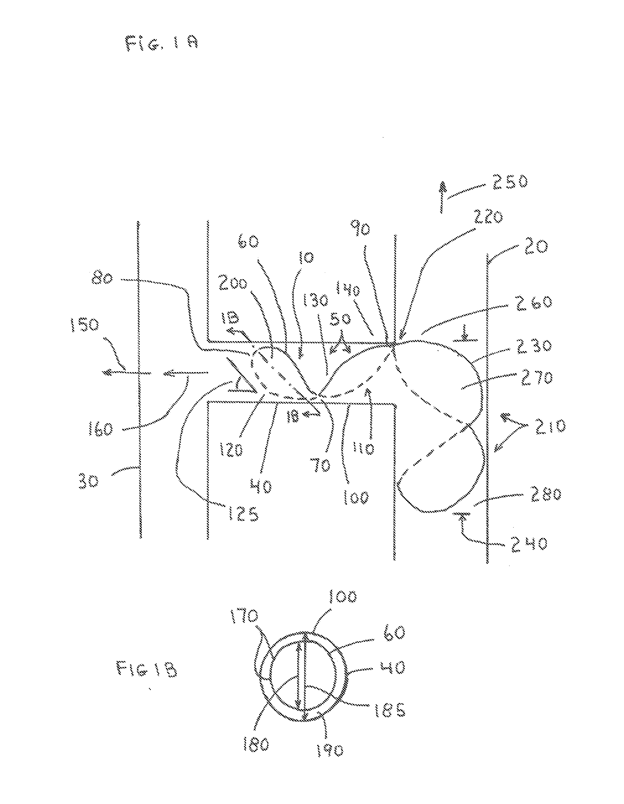
[0033]The present invention is an occlusion device (10) (FIG. 1A) that is passed percutaneously or transcutaneously into a truncal vessel (20) or deep vein (30) and delivered to a perforator vein or other branch vessel (40) that extends from the truncal vessel (20) or is delivered directly into a truncal vessel (20) or branch vessel (40) to occlude such vessel directly. Access to the truncal vessel (20) can be from a distal site such as a GSV or a SSV near the ankle or access can be from a proximal site into the GSV or SSV near the inguinal fold or near the knee. The device can also be delivered percutaneously to an artery or other tubular member of the body to create an occlusion.

[0034]FIGS. 1A and 1B show a first embodiment of the present invention as it applies to occlusion of a perforator vein or other branching vessel (40) off of a truncal vein such as a saphenous vein or other truncal vessel (20). The occlusion device (10) is comprised of a branch portion (50) that extends int...


PUM


Abstract

A low profile occlusion device for percutaneous or direct transcutaneous placement into a vein or other tubular vessel of the body. Two wires form one or more loops having a thin cover disposed between them. The loop forms a beveled angle within the blood vessel and the cover prevents blood flow through the vessel. An additional loop can be present to prevent device embolization or device migration. The occlusion device is delivered to a vein such as an incompetent perforator vein or other incompetent vein through a small flexible sheath. Ultrasound guidance is used to position the occlusion device which can be repositioned within the vessel if necessary.

Description

CROSS REFERENCE TO RELATED APPLICATIONS[0001]This nonprovisional patent application makes reference to and includes information found in the provisional patent applications No. 61 / 465,544 entitled “Branch and Truncal Vessel Occluder” filed 21 Mar. 2011 and 61 / 518,267 entitled “Branch and Truncal Vessel Direct Occluder” filed 3 May 2011, both by William J. Drasler.FIELD OF THE INVENTION[0002]This invention relates to an implanted device that is placed percutaneously or transcutaneously into a lumen of a tubular member of the body such as a vein or artery or a side branch of a vein or artery to occlude the lumen of the tubular member.BACKGROUND OF THE INVENTION[0003]Superficial veins either below or above the knee can develop incompetent valves with an inability to direct blood from the superficial venous system into the deep system and result in reflux of blood from the deep system into the superficial system. Such reflux can occur at the junction of a superficial vein such as the sa...

Claims


Application Information

Patent Timeline
Patent Type & Authority Applications(United States)
IPC IPC(8): A61M29/00
CPCA61B17/12109A61B2017/12054A61B17/12172
Inventor DRASLER, WILLIAM JOSEPH
Owner DRASLER WILLIAM JOSEPH
Learn More