
Efficient polarized directional backlight

a backlight and efficient technology, applied in the field of displays, can solve problems such as difficulties in using conventional approaches, and achieve the effect of low cost and high electrical efficiency

Active Publication Date: 2012-09-27
REALD SPARK LLC
View PDF8 Cites 116 Cited by
  • Summary
  • Abstract
  • Description
  • Claims
  • Application Information

AI Technical Summary

Benefits of technology

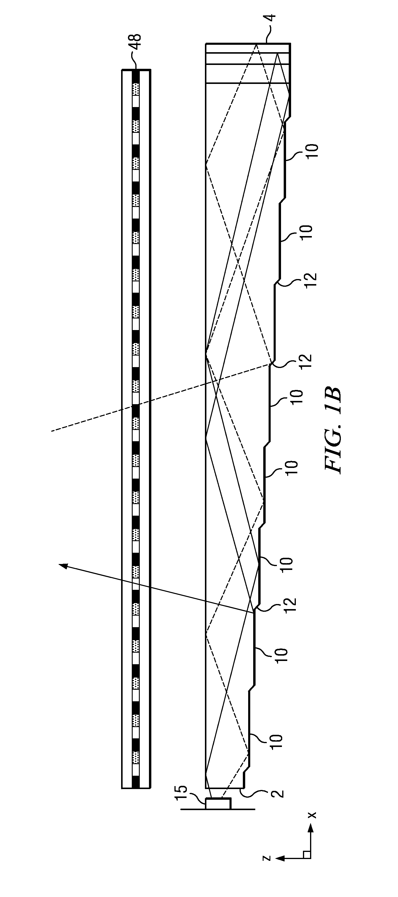
[0006]In addition to the above principles, on the back reflecting surface of the waveguide, a birefringent material can be added to efficiently transform the S-polarized reflected light from the dichroic stack, into returning P-polarized light. Because the returning rays that are now P-polarized by the birefringent material have already achieved the critical angle for exiting the waveguide, the rays transformed to P-polarization can now also exit the waveguide. This is preferred currently over any introduction of birefringence into, or any residual birefringence in, the wedge waveguide's substrate material as it can be tightly controlled. The prescription for the birefringent material is determined by the critical angle of the waveguide material, as will be discussed later.
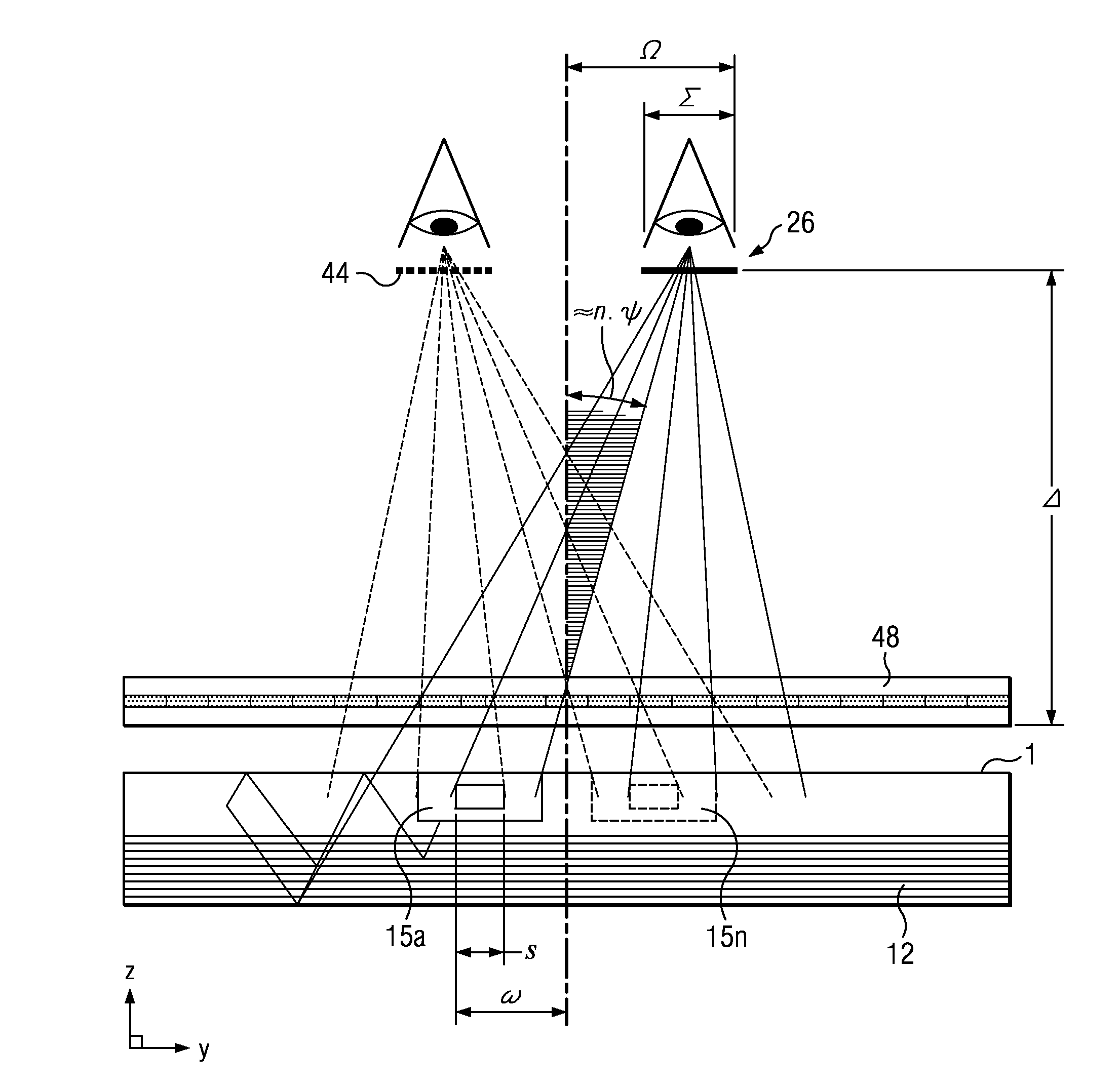
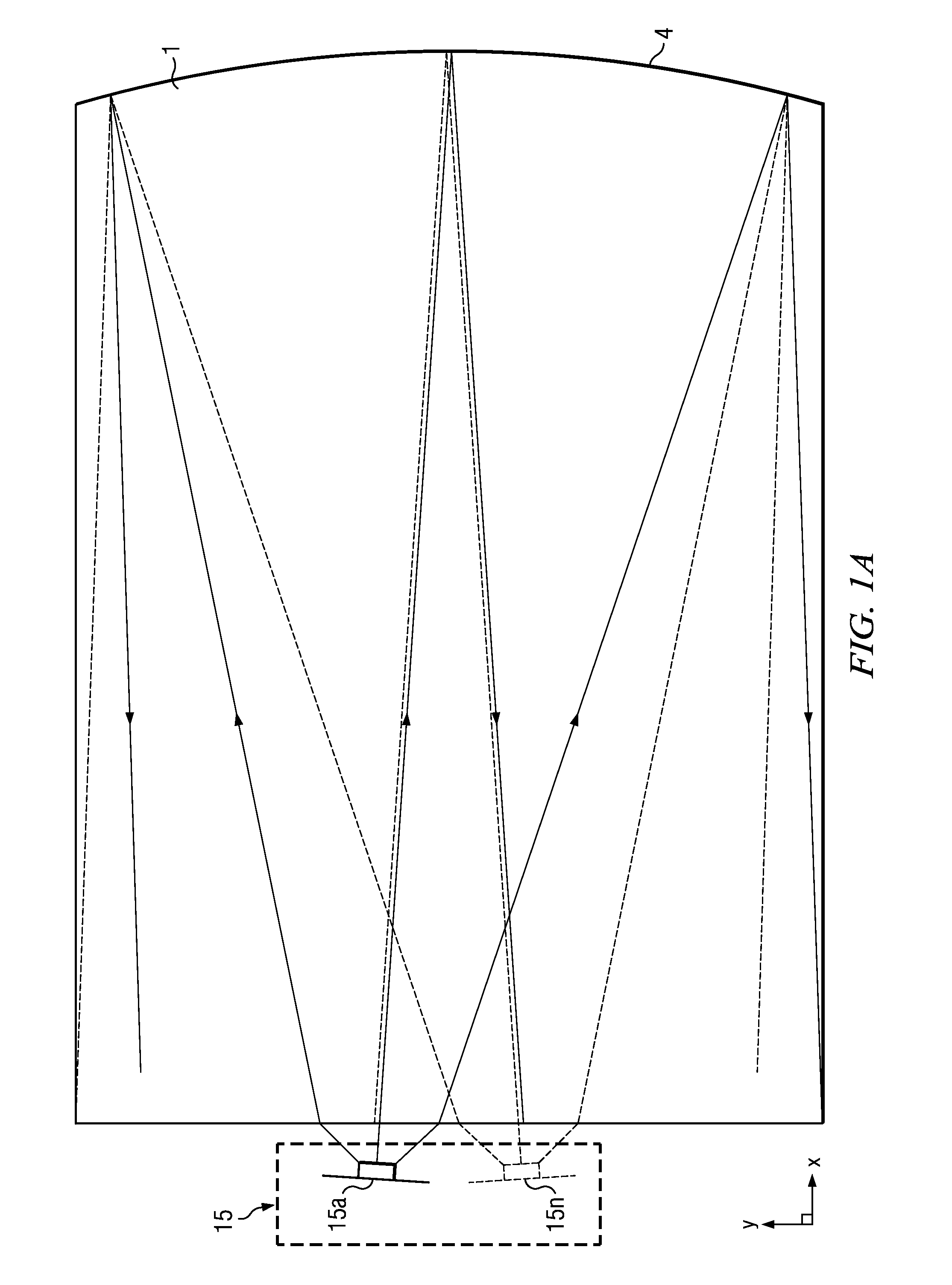
[0011]Embodiments herein may provide an autostereoscopic display with large area and thin structure. Further, as will be described, the optical valves of the present disclosure may achieve thin optical components with large back working distances. Such components can be used in directional backlights, to provide directional displays including autostereoscopic displays. Further, embodiments may provide a controlled illuminator for the purposes of an efficient autostereoscopic display.
[0014]Directional backlights offer control over the illumination emanating from substantially the entire output surface controlled typically through modulation of independent LED light sources arranged at the input aperture side of an optical waveguide. Controlling the emitted light directional distribution can achieve single person viewing for a security function, where the display can only be seen by a single viewer from a limited range of angles; high electrical efficiency, where illumination is only provided over a small angular directional distribution; alternating left and right eye viewing for time sequential stereoscopic and autostereoscopic display; and low cost.

Problems solved by technology

However, it may be difficult to use conventional approaches such as, 3M's Vikuiti™ Dual Brightness Enhancement Film (DBEF), to efficiently polarize output light for illuminating LCDs on top of the added complexity that directionality demands.

Method used


Image

  • Efficient polarized directional backlight
  • Efficient polarized directional backlight
  • Efficient polarized directional backlight

Examples


Embodiment Construction

[0051]Time multiplexed autostereoscopic displays can advantageously improve the spatial resolution of autostereoscopic display by directing light from all of the pixels of a spatial light modulator to a first viewing window in a first time slot, and all of the pixels to a second viewing window in a second time slot. Thus an observer with eyes arranged to receive light in first and second viewing windows will see a full resolution image across the whole of the display over multiple time slots. Time multiplexed displays can advantageously achieve directional illumination by directing an illuminator array through a substantially transparent time multiplexed spatial light modulator using directional optical elements, wherein the directional optical elements substantially form an image of the illuminator array in the window plane.

[0052]The uniformity of the viewing windows may be advantageously independent of the arrangement of pixels in the spatial light modulator. Advantageously, such ...


PUM


Abstract

By introducing a stack of alternating high and low index dichroic material layers on the exit surface of a waveguide for a wedge type directional backlight, natural reflectivity differences between polarized components can be increased, effectively reflecting the vast proportion of S-polarized light rays, while at the same time transmitting the P-polarized light rays, of light impacting the exit surface of the waveguide at an angle sufficient to exit the waveguide. This recovers polarization in wedge type backlight systems, increasing illumination exiting the waveguide. Also, on the back reflecting surface of the waveguide, a birefringent material can be added to efficiently transform S-polarized reflected light from the dichroic stack, into returning P-polarized light. Because returning rays that are now P-polarized by the birefringent material have already achieved the critical angle for exiting the waveguide, the rays transformed to P-polarization can now also exit the waveguide, increasing waveguide illumination.

Description

CROSS-REFERENCE TO RELATED CASES[0001]The present application is a conversion of and thus claims priority to U.S. Provisional Pat. App. Ser. No. 61 / 486,021, entitled “Efficient polarized directional backlight,” filed May 13, 2011, which is incorporated herein by reference in its entirety. The present application further claims priority to and is a continuation in part of U.S. patent application Ser. No. 13 / 300,293, entitled “Directional flat illuminators,” filed Nov. 18, 2011, which claims priority to U.S. Prov. Pat. App. Ser. No. 61 / 415,810, entitled “Directional flat illuminators,” and filed Nov. 19, 2010, all of which are also herein incorporated by reference in their entirety.TECHNICAL FIELD[0002]The present disclosure generally relates to displays, and more specifically, to two dimensional and three dimensional display technologies and components.BACKGROUND[0003]Generally, current display technologies may include functionality to deploy, view and / or display three dimensional (3...

Claims


Application Information

Patent Timeline
IPC IPC(8): F21V9/14G02B5/30G02B30/26
CPCG02B27/225G02B6/0056G02B6/0048G02B27/2264G02B30/26G02B30/24
Inventor ROBINSON, MICHAEL G.
Owner REALD SPARK LLC
Learn More