Eureka AIR delivers breakthrough ideas for toughest innovation challenges, trusted by R&D personnel around the world.

Electric energy management socket

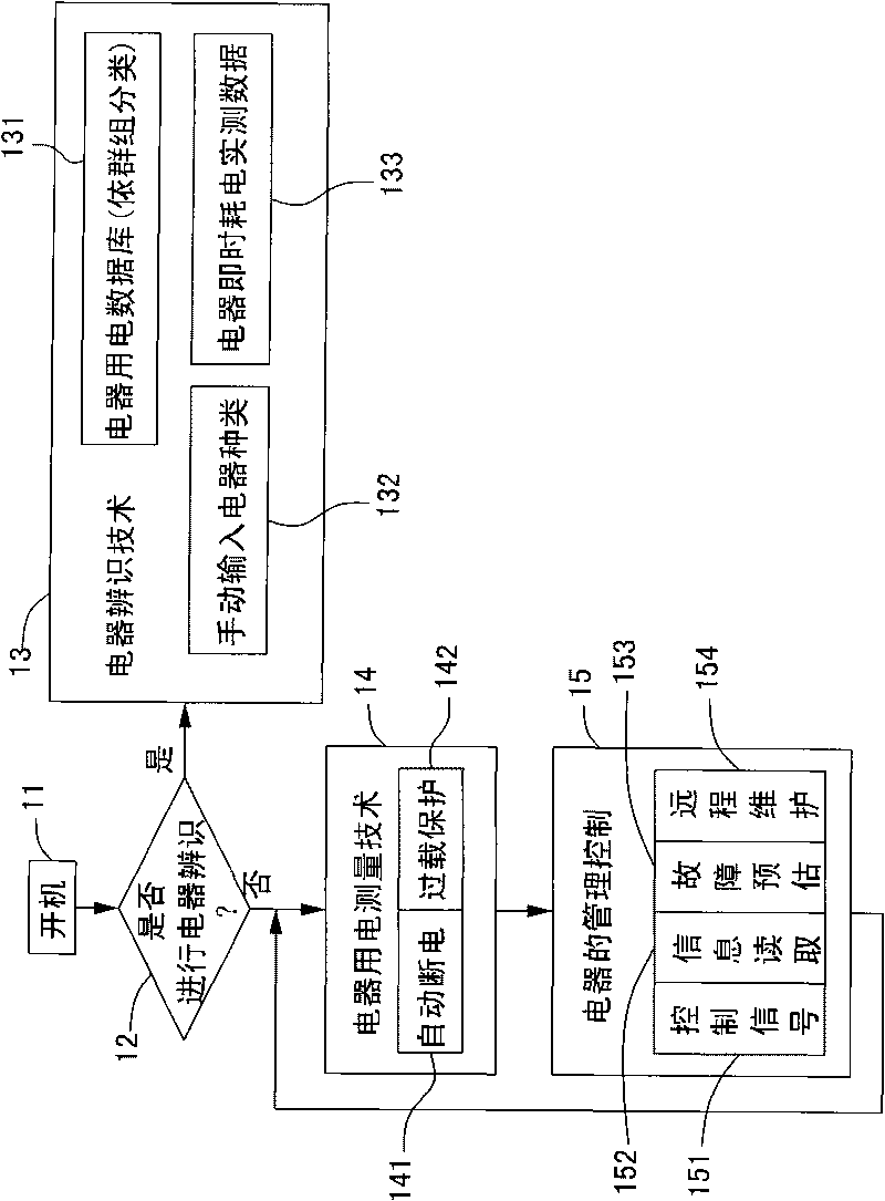
A technology of power management and sockets, applied in circuits, electrical components, instruments, etc., can solve the problems of not involving the working mode remote control and electrical appliances, lack of system concepts and processes, etc.

Active Publication Date: 2010-06-16
IND TECH RES INST
View PDF1 Cites 41 Cited by
  • Summary
  • Abstract
  • Description
  • Claims
  • Application Information

AI Technical Summary

Problems solved by technology

The currently known patents are mainly related to the hardware structure and style of the remote control, and there are no related patents related to the working mode and how to set the connection between the remote control and the electrical appliance, lacking a complete system concept and process

Method used


Image

  • Electric energy management socket
  • Electric energy management socket
  • Electric energy management socket

Examples


no. 1 example

[0056] Change the detection sampling frequency according to the needs, and has the detection sampling frequency conversion function. Taking the current domestic voltage frequency of 60Hz as an example, it includes the following two modes:

[0057] When entering the electrical self-diagnosis detection mode, the number of sampling times in this embodiment is 128 times, and the sampling frequency is 7.68KHz, and the detection sampling frequency signal conversion is performed to speed up the detection frequency of the power signal to be sampled, which can indeed increase the sampling frequency of the measured value and precision.

[0058] When detecting the power consumption mode of electrical appliances normally, the number of sampling in this embodiment is 64 times, and the sampling frequency is 4.096KHz, and then it is returned to the normal power signal detection frequency, so that the system has extra time for other data processing, such as communication transmission and rece...

no. 2 example

[0060] Create an identification database

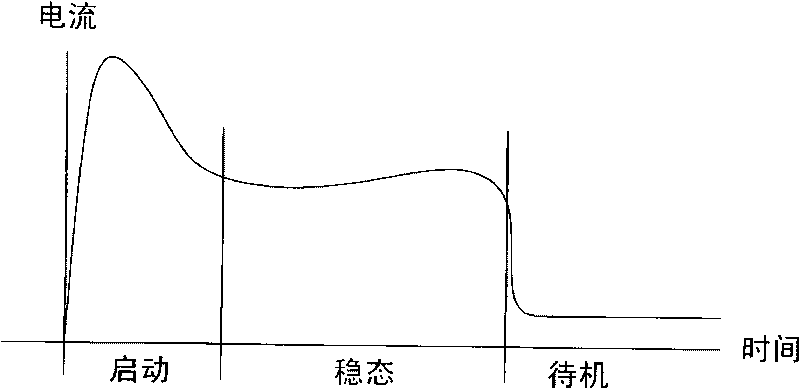
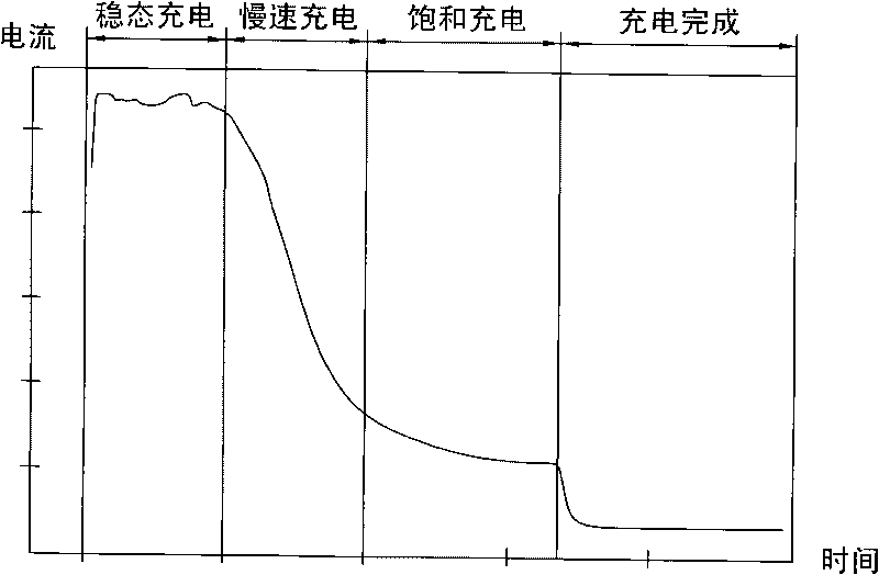
[0061] see Figure 2AAs shown, it is a graph used by the present invention to identify electric power consumption of electrical appliances. Its ordinate (Y axis) is the current (I) and the abscissa (X axis) is time (Time). Because the voltage of the electrical appliance is quite fixed, it is Domestically, it is either 110V or 220V, so the voltage data is quite fixed, so the ordinate curve can only be discussed for the current (I). The existing built-in database: all electrical appliances in the family are classified according to the database column, and according to the electrical consumption Electricity curve, including the following three database fields: start-up, steady-state (normal) power and standby power consumption information, respectively build a table based on this and store it in the memory storage unit, for the system to use as an electrical category database for identifying household appliances .

[0062] When the dev...

no. 3 example

[0073] Instant Appliances Learning Database

[0074] If the electrical appliance is a newly added electrical appliance, the original voltage and current measurement function of the system can be used to directly collect the new electrical category database online.


PUM


Abstract

The invention relates to an electric energy management socket which is connected with an electric device and is used for supplying electricity to the electric device. The socket comprises a sensing circuit, an electric device identification database, a micro control unit and a power circuit, wherein the sensing circuit is used for detecting the voltage or current values of the electric device on the socket and outputting the values; the electric device identification database is used for storing the current parameter values of at least a specific electric product; the micro control unit is used for receiving the values output by the sensing circuit, operates and is compared with the electric device identification database after analog / digital converting of signals to identify whether the electric device is the specific electric device. The power circuit is used for providing power source to the above component.

Description

technical field [0001] The invention relates to a power management socket, in particular to an intelligent remote control power management socket. Background technique [0002] Regarding the research and development of electronic products to reduce standby power consumption, although it is known that there are quite a few related patents at home and abroad, there are not many technologies for realizing intelligent remote control standby power consumption by using remote control appliances or wired control modes. The currently known patents are mainly related to the hardware structure and style of the remote control, and there are no related patents related to the working mode and how to set the connection between the remote control and the electrical appliance, lacking a complete system concept and process. [0003] The intelligent remote control power management socket proposed by the present invention will cooperate with the energy consumption characteristics of household ...

Claims


Application Information

Patent Timeline
IPC IPC(8): H01R13/66G05B15/02
Inventor 邹玉萍林政廷王安平陈俊宇何无忌
Owner IND TECH RES INST
Why Eureka
Eureka Blog
Learn More