Eureka AIR delivers breakthrough ideas for toughest innovation challenges, trusted by R&D personnel around the world.

Lithium air battery

a battery and air technology, applied in the field of lithium air batteries, can solve the problems of battery performance deterioration, battery deterioration, performance significantly deterioration, etc., and achieve the effect of lowering the charge and discharge characteristics of the air battery resulting from anode deterioration, improving battery output, and reducing the charge and discharge characteristics of the air battery

Inactive Publication Date: 2012-09-20
SONY CORP
View PDF4 Cites 47 Cited by
  • Summary
  • Abstract
  • Description
  • Claims
  • Application Information

AI Technical Summary

Benefits of technology

[0023]In Non-patent document 1, the aqueous electrolytic solution is used in a region closer to the cathode to take in the air, the nonaqueous electrolytic solution is used in a region closer to the anode, and both the electrolytes are separated by the solid electrolyte film. Therefore, even if moisture in the air is mixed in the cathode, since the anode is separated by the solid electrolyte, the moisture is not mixed in the nonaqueous electrolytic solution, and deterioration of the battery is allowed to be prevented. However, in Non-patent document 1, the alkali aqueous electrolytic solution is used. Therefore, carbon dioxide in the air and the aqueous electrolytic solution react with each other, and performance of the aqueous electrolytic solution is lowered. As a result, there is a disadvantage that performance of the battery is deteriorated.
[0026]The present invention is made to solve the foregoing problems, and it is an object of the present invention to provide a lithium air battery capable of being used for a long time with little deterioration due to influence by moisture and carbon dioxide in the air in which oxygen supply to a porous cathode is not inhibited by an air electrode current collector.
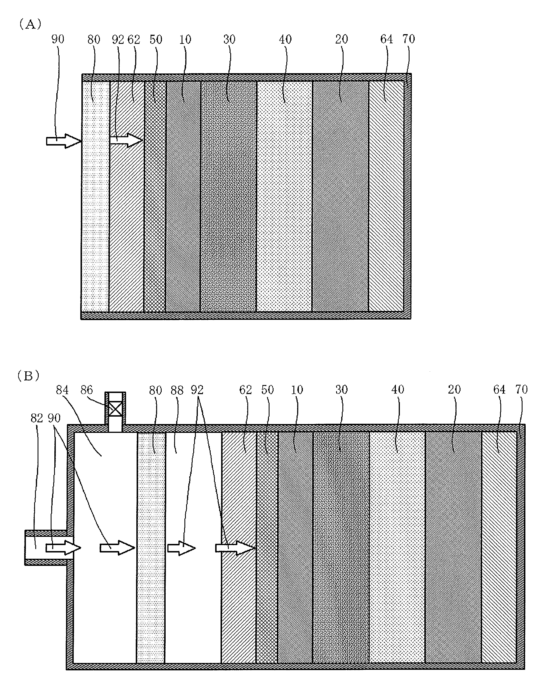
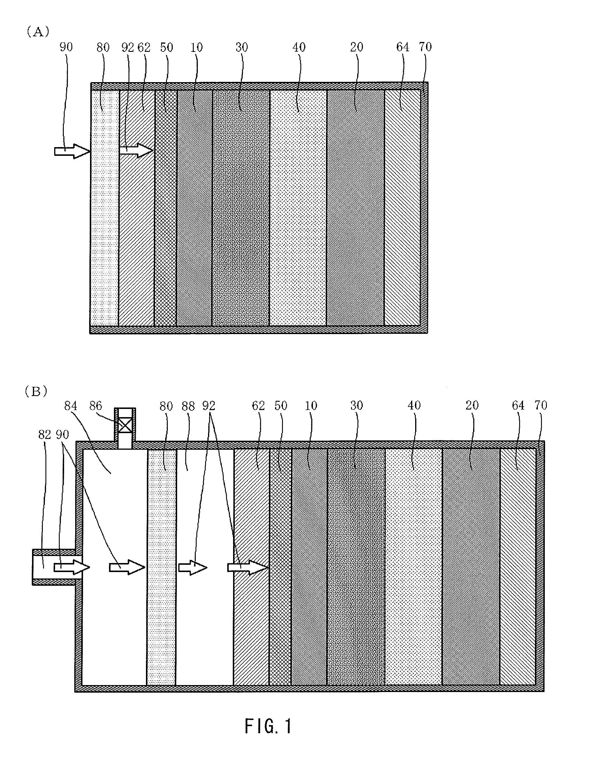
[0028]According to the present invention, the anode that extracts lithium ions, the air electrode current collector made of the porous material, the porous cathode containing the conductive material, the diffusion layer that is arranged between the air electrode current collector and the porous cathode and is made of the conductive material, and the nonaqueous electrolyte arranged between the anode and the porous cathode are included. Therefore, oxygen that has passed through the air electrode current collector made of the porous material is diffused by the diffusion layer, and accordingly oxygen is supplied to the entire surface of the porous cathode without inhibiting oxygen supply to the porous cathode by the air electrode current collector. In addition, as a result of reaction between oxygen and lithium in the entire porous cathode, battery output is improved. Further, since the nonaqueous electrolyte is used without using an alkali solution electrolyte, a lithium air battery with a little deterioration due to influence by moisture and carbon dioxide in the air is allowed to be provided. Further, by using a hydrophobic nonaqueous electrolyte, oxygen and moisture are less likely to be dissolved in the nonaqueous electrolyte, movement of oxygen and the moisture taken in from a region closer to the air electrode to the anode thorough the nonaqueous electrolyte is allowed to be suppressed, and anode deterioration caused by oxidation reaction and hydrolysis reaction is allowed to be suppressed. Therefore, lowering of charge and discharge characteristics of the air battery resulting from anode deterioration due to oxygen and moisture is allowed to be suppressed. Accordingly, a lithium air battery with further little deterioration due to influence by oxygen and moisture in the air is allowed to be provided.

Problems solved by technology

Therefore, in the case where moisture in the air is mixed in the nonaqueous electrolyte, the batteries may be deteriorated.
As a result, there is a disadvantage that performance of the battery is deteriorated.
In the existing lithium air batteries and the existing lithium air secondary batteries, there is a disadvantage that being influenced by moisture and carbon dioxide in the air, the performance is significantly deteriorated and long-term usage thereof is not available.

Method used


Image

  • Lithium air battery
  • Lithium air battery
  • Lithium air battery

Examples


embodiment

[0046]FIG. 1 illustrates a schematic structure of a lithium air battery according to an embodiment of the present invention.

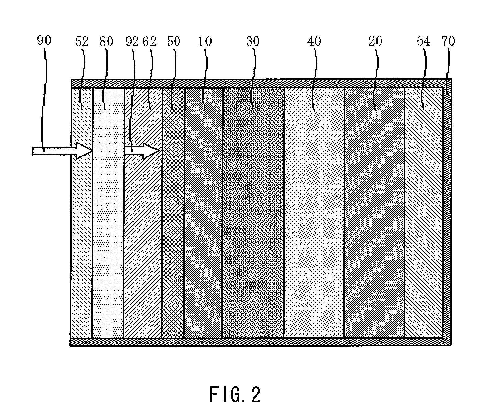
[0047]The lithium air battery illustrated in FIG. 1(A) includes an oxygen permselective film 80 that is less likely to transmit moisture vapor and selectively transmits oxygen, an air electrode current collector 62 made of a conductive porous material, a porous diffusion layer 50 that is arranged between the air electrode current collector 62 and a porous cathode 10 and is made of a conductive material, the porous cathode 10 containing a conductive material and a catalyst material, a separator 30 that is less likely to transmit moisture vapor, a nonaqueous electrolyte 40, an anode 20 that extracts lithium ions, an anode current collector 64, and an outer package 70 in which these respective layers (films) are contained. To prevent deterioration of the anode 20 due to oxygen and moisture taken in from the region closer to the air electrode side, the nonaqueous e...


PUM

PropertyMeasurementUnit
diameteraaaaaaaaaa
conductiveaaaaaaaaaa
oxygen permselectiveaaaaaaaaaa

Abstract

A lithium air battery capable of being used for a long time with little deterioration due to influence by moisture in the air in which oxygen supply to a porous cathode is not inhibited by an air electrode current collector is provided. The lithium air battery includes an oxygen permselective film that is less likely to transmit moisture vapor and that selectively transmits oxygen, an oxygen chamber that stores oxygen, an air electrode current collector made of a porous material, a diffusion layer that is arranged between the air electrode current collector and a porous cathode and is made of a conductive material, the porous cathode containing a conductive material and a catalyst material, a separator that is less likely to pass moisture vapor, a nonaqueous electrolyte, an anode that extracts lithium ions, and an anode current collector. The lithium air battery may have a water-repellent layer.

Description

TECHNICAL FIELD[0001]The present invention relates to a lithium air battery.BACKGROUND ART[0002]To realize low carbon society, developing batteries having a significantly increased capacity is urgently needed.[0003]In recent years, lithium air batteries and lithium air secondary batteries achieving a significantly increased capacity by taking in oxygen in the air have been actively developed. Examples of reports on the air batteries include the following.[0004]In the after-mentioned Non-patent document 1 titled “Air Battery,” the following description is given. FIG. 5(A) corresponds to FIG. 1 shown in Patent document 1, which illustrates a schematic view of an air battery.[0005]The air battery according to the invention of Patent document 1 includes an anode, a cathode that has a catalyst which contains cerium and in which cubic capacity of fine pores being from 5 nm to 35 nm both inclusive in diameter is equal to or larger than 0.15 ml / g, and a nonaqueous electrolyte existing betwe...

Claims


Application Information

Patent Timeline
Patent Type & Authority Applications(United States)
IPC IPC(8): H01M8/22
CPCH01M12/08H01M12/06Y02E60/10
Inventor UESAKA, SHINICHI
Owner SONY CORP
Why Eureka
Eureka Blog
Learn More