High voltage semiconductor device and driving circuit
a driving circuit and semiconductor technology, applied in electronic switching, pulse generators, pulse techniques, etc., can solve the problems of relatively large electric current increase losses, achieve high switching response speed, reduce power loss, and block high voltage
- Summary
- Abstract
- Description
- Claims
- Application Information
AI Technical Summary
Benefits of technology
Problems solved by technology
Method used
Image
Examples
first embodiment
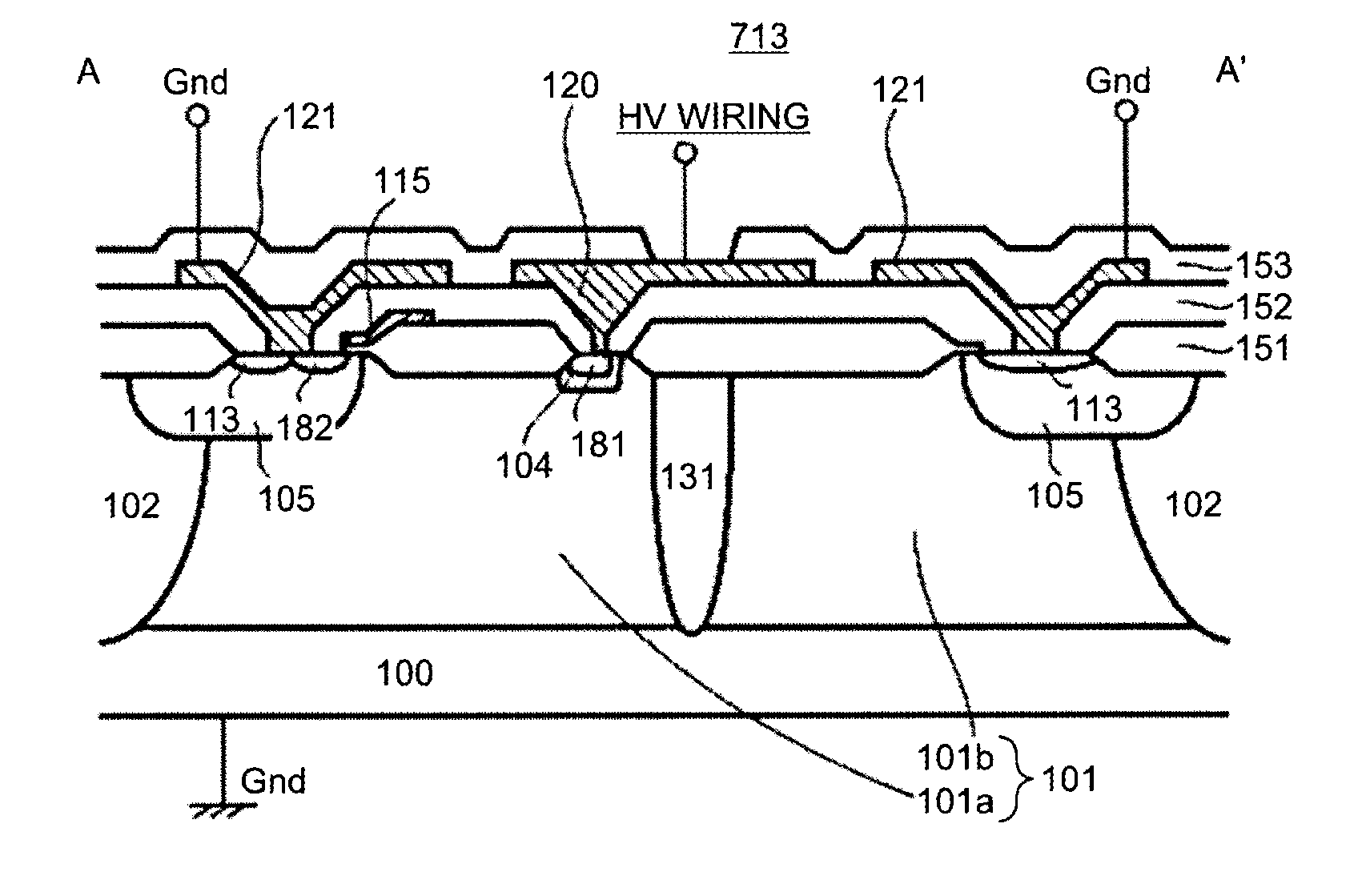
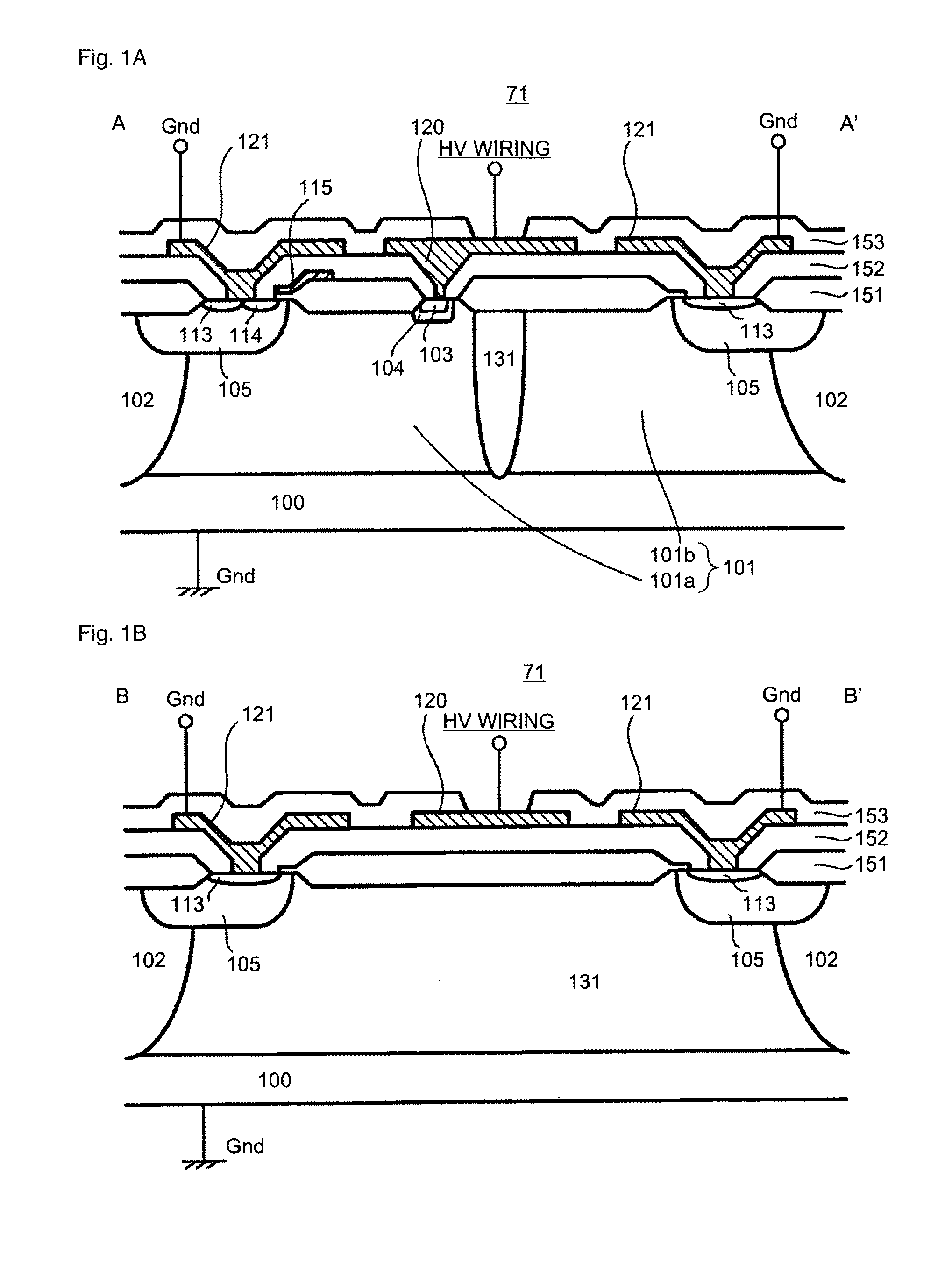
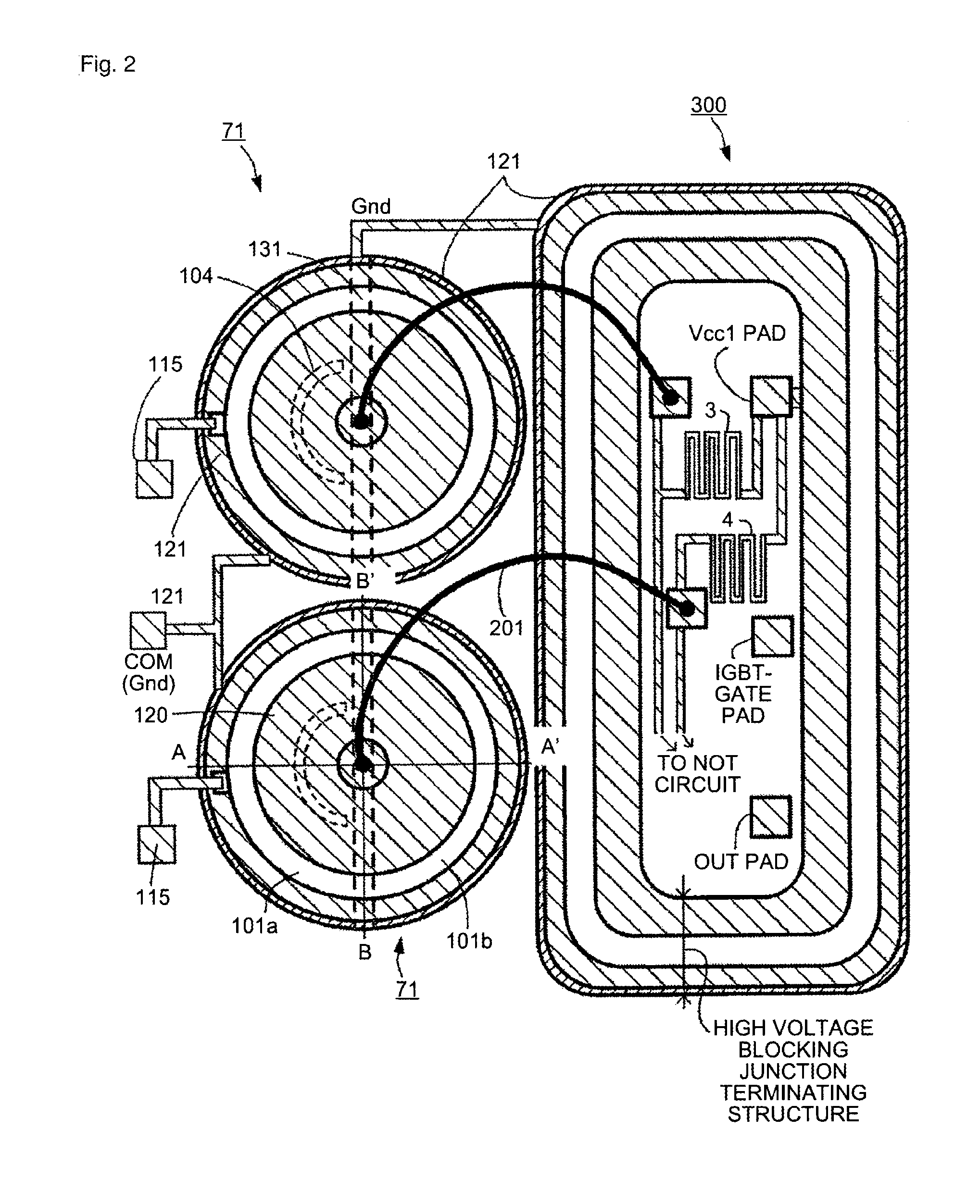
[0076]A first embodiment will be explained with reference to FIG. 1A to FIG. 5, and FIG. 13. FIGS. 1A and 1B are cross sectional views of a principal part of a high voltage MOSFET according to the first embodiment of the invention. FIG. 2 is a plan view of a principal part of a high voltage IC according to the invention. In FIG. 2, a level shift circuit including the high voltage MOSFET and a driving circuit equipped with a floating electric potential region are formed on a single semiconductor substrate (hereinafter, for FIGS. 6 and 9A as well). A cross sectional view taken along line A-A′ in FIG. 2 corresponds to the cross sectional view shown in FIG. 1A and a cross sectional view taken along line B-B′ in FIG. 2 corresponds to the cross sectional view shown in FIG. 1B. In FIG. 2, of semiconductor regions in a high voltage MOSFET 71, only an n offset region 104 and a p−-region 131 are shown by broken lines.
[0077]The high voltage MOSFETs 71 shown in FIGS. 1A and 1B correspond to the...
second embodiment
[0102]FIG. 6 is a plan view showing a principal part of a high voltage IC according to a second embodiment of the invention. A cross sectional view taken along line A-A′ in FIG. 6 is the same as the cross sectional view of the first embodiment shown in FIG. 1A.
[0103]As shown in FIG. 6, a high voltage MOSFET 72 differs from the high voltage MOSFET 71 shown in FIG. 2 in that the plane figure of the p−-region 131 is formed into a V-shape. With the n−-type region 101 divided by the V-shaped p−-region 131 in this way, the area of the section functioning as a MOSFET becomes approximately one-fourth of the area of the corresponding section of the related MOSFET. This can reduce a parasitic output capacitance in the high voltage MOSFET 72 by 60 percent up to a maximum of the order of 75 percent compared with that of the example of a related high voltage MOSFET.
[0104]As explained, according to the second embodiment, the effects of the first embodiment can be achieved.
third embodiment
[0105]FIG. 7 is a plan view showing a principal part of the high voltage MOSFET 73 according to a third embodiment of the invention. A high voltage MOSFET 73 differs from the high voltage MOSFET 72 shown in FIG. 6 in that the n−-type region 101b (a region at a floating electric potential) divided by the p−-region 131 is formed of a plural sections. In this way, the region divided by the p−-region 131 is not necessarily one region but can be formed of a plural regions.
[0106]As explained, according to the third embodiment, the effects of the first embodiment can be achieved.
PUM
 Abstract
Description
Claims
Application Information
 - R&D
- Intellectual Property
- Life Sciences
- Materials
- Tech Scout
- Unparalleled Data Quality
- Higher Quality Content
- 60% Fewer Hallucinations
Browse by: Latest US Patents, China's latest patents, Technical Efficacy Thesaurus, Application Domain, Technology Topic, Popular Technical Reports.
© 2025 PatSnap. All rights reserved.Legal|Privacy policy|Modern Slavery Act Transparency Statement|Sitemap|About US| Contact US: help@patsnap.com


