
High-Strength Bolt

a bolt and high-strength technology, applied in the field of high-strength bolts, can solve the problems of delayed fracture resistance, difficult softening of materials, and hindering the strengthening of high-strength bolts, and achieve excellent ductility, delayed fracture resistance, and high strength level

Active Publication Date: 2012-09-13
NAT INST FOR MATERIALS SCI +2
View PDF14 Cites 42 Cited by
  • Summary
  • Abstract
  • Description
  • Claims
  • Application Information

AI Technical Summary

Benefits of technology

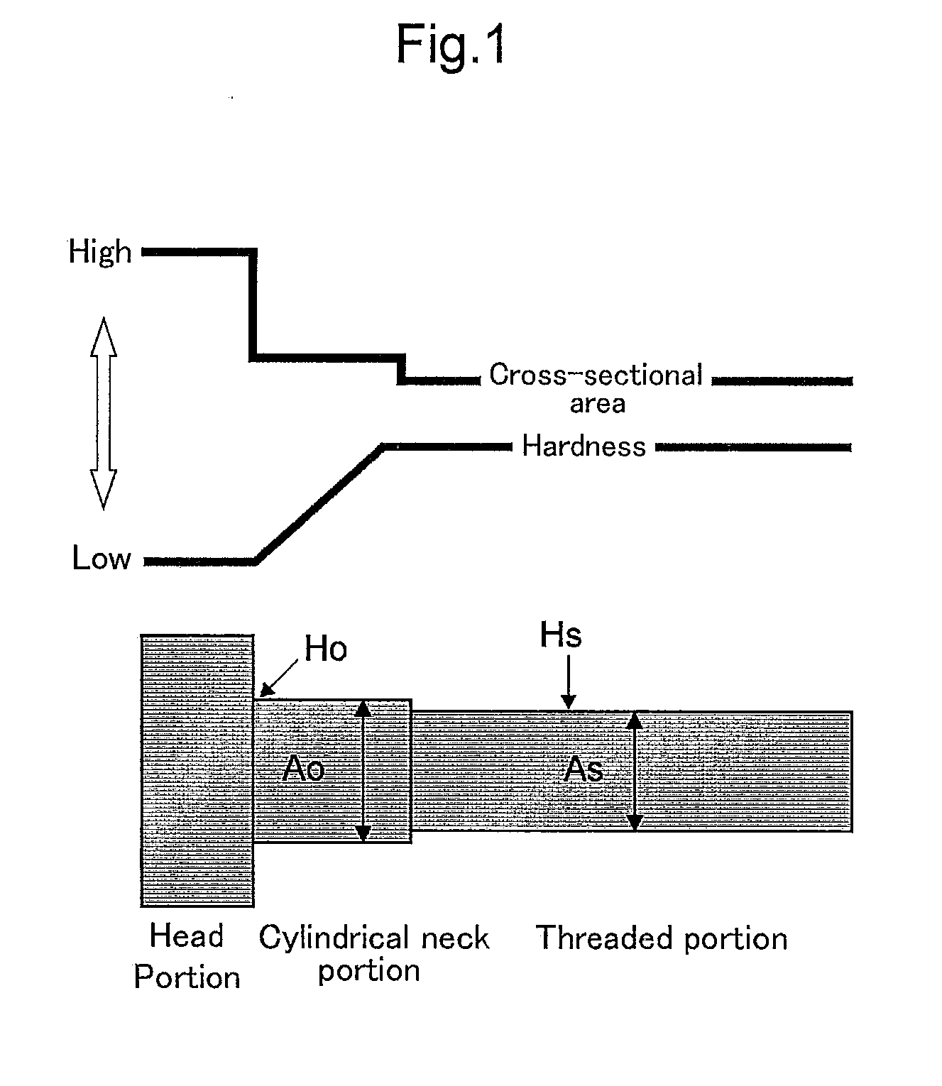
The present invention provides a high-strength bolt with excellent ductility and resistance to delayed fracture, which has not been possible in conventional bolt designs. The bolt has a tensile strength of 1,200 MPa or more and meets the requirements for high-strength materials in structures such as automotive parts. The bolt has a complex structure, including a cylindrical neck portion and a threaded portion, which makes it difficult to soften the material and form a head portion by cold heading. The invention solves this problem by using a specific method to produce the bolt with good formability, resistance to delayed fracture, and impact toughness.

Problems solved by technology

In the steel material having a tensile strength of more than 1,200 MPa, especially a delayed fracture is a serious problem, which hinders strengthening of the high-strength bolt.
The cause of the delayed fracture is thus the hydrogen which is diffused and concentrated in the steel at room temperature.
However, it is pointed out that, with respect to the above high-strength steel material, it is difficult to soften the material and form a head portion by cold heading, and in the case of bolt shape be defined in accordance with Japanese Industrial Standard (JIS), the delayed fracture property has not yet been completely overcome (Non-Patent Document 2).
Since the quenching and tempering process of bolt is complicated, there is a production method in which the quenching and tempering treatment is omitted (untempered bolt).
However, since these methods are performed on condition that the bolt is formed in cold working, a shape and a size of the bolt are limited.
Further, since it is necessary to set an amount of carbon to 0.7 percent by weight or more, a remarkable improvement of impact toughness cannot be expected.

Method used


Image

  • High-Strength Bolt
  • High-Strength Bolt
  • High-Strength Bolt

Examples


examples

[0060]Table 1 shows chemical compositions of the steels used for bolt materials. Material A includes the chemical composition of the steel which showed excellent performance in the delayed fracture resistance disclosed in Reference 2. Material B corresponds to an SCM440 steel according to JIS. For the quenched and tempered materials, steel bars with a cross section of approximately 2 cm2 were prepared. The steel bars of Materials A and B were quenched from 950. and 920., respectively, and then tempered at 500. and 400., respectively, for 1 hour. As for the particle dispersion type fibrous grain structure materials, squared bars with a cross section of approximately 9 cm2 were prepared. Then, the bars of Materials A and B were quenched from 950. and 920., respectively, to thereby obtain full martensite structures of almost 100 percent by volume. Herein, the prior austenite grain size in the quenched structure was approximately 50 μm. Subsequently, Materials A and B were tempered at 5...


PUM

PropertyMeasurementUnit
tensile strengthaaaaaaaaaa

Abstract

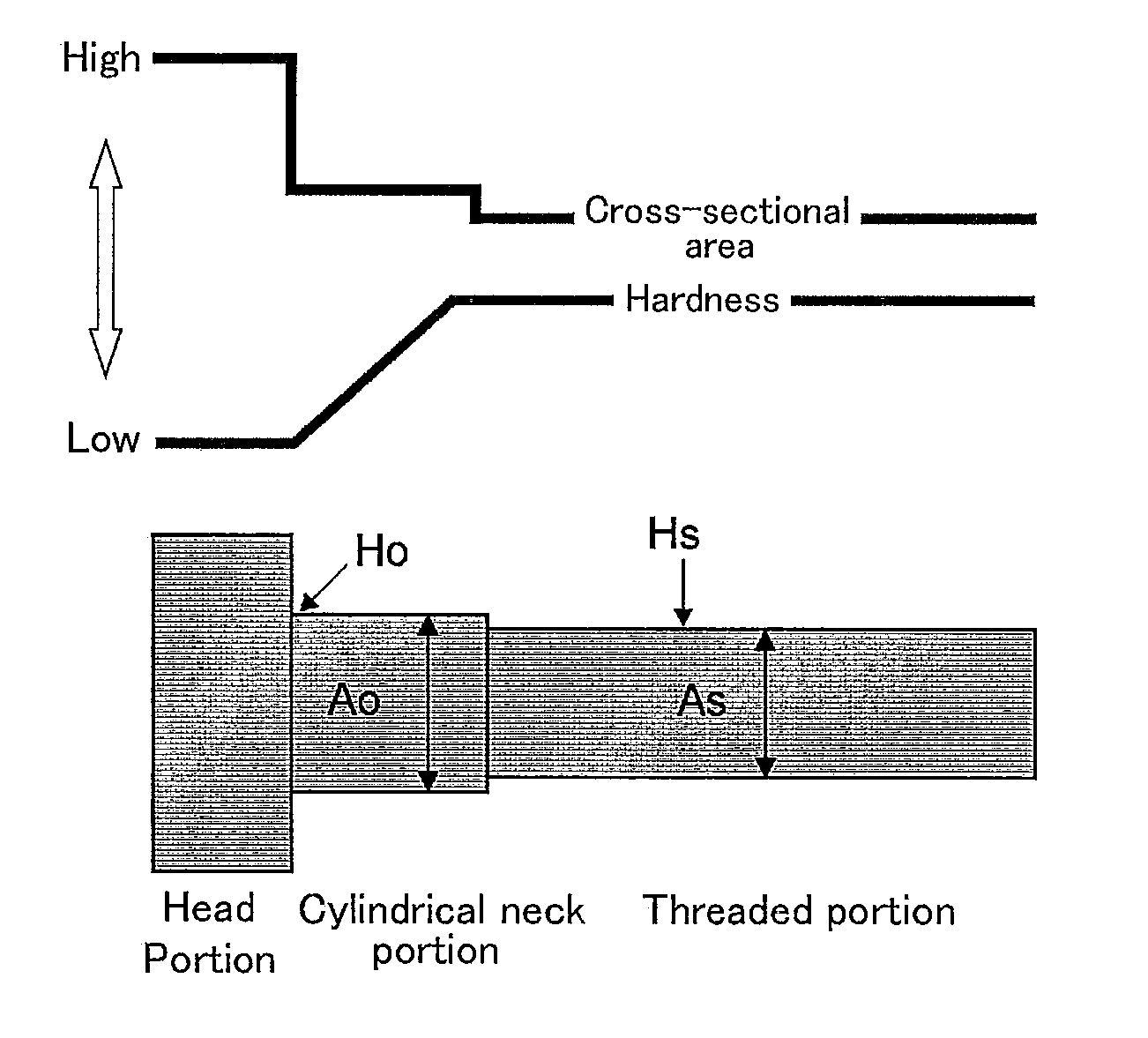
Provided is a high-strength bolt which has a tensile strength of 1,200 MPa or more while exhibiting excellent ductility and delayed facture resistance, and further has an excellent impact toughness which had not been obtained in the conventional high-strength bolt. The high-strength bolt has a tensile strength of 1.2 GPa or more and includes a threaded portion and cylindrical neck portion. The bolt has K of 0.8 or more and satisfies Ho<Hs, where K is defined by the equation: (Ao×Ho) / (As×Hs)=K, in which Ao is an effective cross-sectional area of the cylindrical neck portion with a diameter larger than that of the threaded portion, Ho is a Vickers hardness of a portion at which Ao is measured, As is an effective cross-sectional area of the threaded portion, and Hs is a Vickers hardness of the threaded portion.

Description

TECHNICAL FIELD[0001]The present invention relates to a high-strength bolt having a tensile strength of 1,200 MPa or more.BACKGROUND ART[0002]Recent trends of increase in size of structures and weight saving of automotive parts have been raising a need for high-strength metal materials stronger and tougher than ever. Among these, steel materials, such as sheet steel and shaped steel, have been demanded to have high strength. At the same time, there has been also demanded strengthening of bolt that is used for jointing those steel materials (see, for instance, Patent Document 1 and Non-Patent Document 1).[0003]Mechanical properties required for materials of the bolt are: (1) good formability; (2) high resistance to delayed fracture; (3) excellent resistance to environmental deterioration; (4) excellent impact toughness; and the like. However, these properties and an increase in strength of materials are in a trade-off relationship.[0004]In the steel material having a tensile strength...

Claims


Application Information

Patent Timeline
Patent Type & Authority Applications(United States)
IPC IPC(8): F16B35/00
CPCC21D8/06C21D9/0093C22C38/001C22C38/02F16B35/041C22C38/06C22C38/22C22C38/34C22C38/04C21D9/00C22C38/58F16B35/00
Inventor KIMURA, YUUJIINOUE, TADANOBUMURASAKI, SHUJIFUKUDA, MATAICHI
Owner NAT INST FOR MATERIALS SCI
Learn More